Friday, December 27, 2013

Non Inverting Summing Amplifier

Here's the circuit:
Non Inverting Summing Amplifier, general case

We start by finding the equations for $V_{+}$ and $V_{-}$:
\[V_{-} = V_{out} \frac{R_g}{R_g +R_f}\]
The currents to the $V_{+}$ node have the same subscripts as the voltages and resistances. We now have a bunch of equations:
\[V_{1} - V_{+} = I_{1}R_{1}\\
V_{2} - V_{+} = I_{2}R_{2} \]
and so on to:
\[V_{n} - V_{+} = I_{n}R_{n} \]
We also have
\[I_{1}  +  I_{2} +\cdots + I_{n} = 0 \]
So by arranging the equations in this form:
\[\frac{V_{n} - V_{+}}{R_{n}} = I_{n} \]
we get:
\[\frac{V_{1} - V_{+}}{R_{1}}+\frac{V_{2} - V_{+}}{R_{2}}+\cdots +\frac{V_{n} - V_{+}}{R_{n}} = 0 \]
which can be simplified to:
\[V_{+}=\frac{V_{1}R_{1}R_{2}\cdots R_{n}/R_1+V_{2}R_{1}R_{2}\cdots R_{n}/R_2+\cdots +V_{n}R_{1}R_{2}\cdots R_{n}/R_n }{R_{1}R_{2}\cdots R_{n}/R_1+R_{1}R_{2}\cdots R_{n}/R_2+R_{1}R_{2}\cdots R_{n}/R_n}  \]
(Hope I got that notation right...)

Using the golden op amp rules we now set $V_{+}= V_{-}$ and get:
\[V_{out} \frac{R_g}{R_g +R_f}=\frac{V_{1}R_{1}R_{2}\cdots R_{n}/R_1+V_{2}R_{1}R_{2}\cdots R_{n}/R_2+\cdots +V_{n}R_{1}R_{2}\cdots R_{n}/R_n }{R_{1}R_{2}\cdots R_{n}/R_1+R_{1}R_{2}\cdots R_{n}/R_2+R_{1}R_{2}\cdots R_{n}/R_n} \Rightarrow \\
 V_{out} =\frac{R_g+R_f}{R_g } \frac{V_{1}R_{1}R_{2}\cdots R_{n}/R_1+V_{2}R_{1}R_{2}\cdots R_{n}/R_2+\cdots +V_{n}R_{1}R_{2}\cdots R_{n}/R_n }{R_{1}R_{2}\cdots R_{n}/R_1+R_{1}R_{2}\cdots R_{n}/R_2+R_{1}R_{2}\cdots R_{n}/R_n} \]
If we want to, we can simplify this drastically by setting one or both of these equations:
\[R_{1} = R_{2} = \ \cdots = R_{n} = R\\
R_{g} = R_{f}  \]
Will give us:
\[ V_{out} = 2  \frac{V_{1}+V_{2}+\cdots +V_{n} }{n} \]
To get a unity gain summer we can set:
\[\frac{R_g+R_f}{nR_g } = 1 \Rightarrow \\
R_f = Rg(n-1) \]

That's it. By the way, the schematics I made using xcircuit. It was my first circuit using this tool, but it seems nice enough to try it some more...

Thursday, December 26, 2013

Finished first prototype of MIDI2VC(O)

A lot has been done since the last post. I changed the name of the project to MIDI2VC, since it actually converts MIDI to control voltage, VC.
 I've added the MIDI connector and optocoupler to the input of the board. This is taken from the MIDI electrical specification, I just used another optocoupler, a cheaper one.
 I also added a 1 volt bias to the output of the DAC. I did this since I expect to use a VCO that doesn't go to 0 volt. By adding voltage I can use the whole range of the DAC, between 1 and 5 volts. To do this I first used a voltage divider to divide down the 4.1V reference to 1 volt. This volt is buffered using a unity gain opa amp circuit. The output of the op amp is fed into a non-inverting summing amplifier (also op amp), that sums the one volt and the DAC output. This gives me a range of just below 1 volt to just above 5 volt, giving me a full use of the whole range.
 Since the board is a part of a bigger project, which is 9V powered, i added a linear regulator to power the 5 volt parts. The op amp circuit needs to go above five volts, so it's powered by the 9 volt rail.
I did a full Eagle design using parts I could find on https://www.elfa.se/. The schematics can be seen here: https://dl.dropboxusercontent.com/u/4404053/midi2vc_ver1.pdf. Be aware that I've missed the decoupling caps on the DAC.
 I also made a small board that I ordered from http://oshpark.com/, preview below:

TOP side PCB preview
BOTTOM side PCB preview
The missing caps will be fixed when the other parts of the board are placed. Since this is the first board I've done in Eagle in a long time, I expect there to be some errors. The boards from Oshpark are so cheap (10$ for three of this one), that I can easily take a re spin to fix errors.

I couldn't find a full derivation of the non-inverting summing amplifier circuit in the books or on the net, so I'll do that in the next blog post.

Friday, December 13, 2013

Converting UART data to I2C data

I've managed to get the PIC to receive data over UART and then transmitting the data over I2C, to the DAC.
 Since my aim is to convert key pressings on a MIDI keyboard to voltage control levels for a synthesizer, I only process the "Note on", 0x9X, and "Note off", 0x8X (symbols edited, I had them mixed up) symbols from the UART stream. Right now I'm only reformatting the data so it can be sent over I2C, but this will later be done using a function or a look up table of some sort, so that UART data will translate to the correct control voltage. "Note on" also turns on an LED, and "Note off" turns it off. This will later be used as a gate signal for the synthesizer.
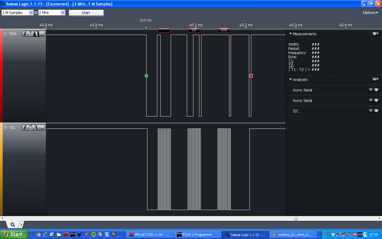
 I used the pickit 2 for sending UART symbols. It's user interface lets you write in HEX, which PUTTY doesn't. The ASCII symbols for 0x8X and 0x9X where pretty strange, so it was a lot easier using the pickit tool. In the other end i used a borrowed Aardwark I2C protocol analyzer in monitoring mode.
 The source code is pretty well commented, so anyone interested in the details can read the comments. The code is starting to become a bit big for posting in the blog, but I don't expect to grow very much more. I intend to add some more features at a later time. These will be MIDI channel settings and handling of several keys being pressed simultaneously.

Successful conversion from UART data to I2C data

1:  //UART to I2C test using PIC12F1822  
2:  #include <xc.h>  
3:    
4:  //Configuration bits  
5:  #pragma config WDTE=OFF, PWRTE = OFF, MCLRE=OFF, BOREN=OFF, FCMEN=OFF, CLKOUTEN = OFF, IESO=OFF, FOSC=INTOSC, CPD=OFF, LVP = ON, BORV = 0  
6:    
7:  //I2C Global variables  
8:  volatile int i2cTransmitCycle; //Counter for I2C transmission cycle steps, which are carried out in the interrupt service routine  
9:  volatile int i2cTransmitInProgress;  
10:  volatile int i2c7bitAddress;  
11:  volatile int i2cData[2];   
12:  volatile int i2cDataCounter; //For indication of which byte is to be sent  
13:  volatile int i2cDataNoBytes; //Number of bytes to be sent  
14:  volatile int i2cDataToBeSent; //For polling in main()  
15:    
16:  //UART Global variables  
17:  volatile int UARTBufferCounter;  
18:  volatile int UARTBuffer[2];  
19:    
20:  //Function prototypes  
21:  int i2cTransmit(int, int [], int);  
22:  void i2cTransferDataArray(int [], int);  
23:  void processUARTSymbol(int);  
24:  void processUARTBuffer(int []);  
25:  void lightLED();  
26:  void toggleLED();  
27:  void unlightLED();  
28:  void init();  
29:  void i2cTransmitProcess();  
30:    
31:  void main() {  
32:    init();  
33:    
34:    extern int i2cTransmitInProgress;  
35:    extern int i2cData[2];  
36:    extern int UARTBufferCounter;  
37:    extern int UARTBuffer[2];  
38:    extern int i2cDataToBeSent;  
39:    
40:    i2cDataToBeSent = 0;  
41:    UARTBufferCounter = 0;  
42:    i2cTransmitInProgress = 0;  
43:    
44:    //Loop forever  
45:    while (1) {  
46:    
47:      //Polling to see if there is any I2C data to be sent  
48:      //I2C data cannot be sent from within the interrupt service routine  
49:      //since the sending I2C data uses several interrupts  
50:      if (i2cDataToBeSent) {  
51:        while (i2cTransmit(0x60, i2cData, 2)) {  
52:        }  
53:        i2cDataToBeSent = 0;  
54:      }  
55:    
56:    }  
57:    
58:  }  
59:    
60:    
61:  //***********************************************************  
62:  //**************Function isr****************  
63:  //Interrupt service routine  
64:  //***********************************************************  
65:  interrupt void isr(void) {  
66:    
67:    
68:    //I2C interrupt  
69:    if (SSP1IF) {  
70:      //Reset SSP interrupt flag  
71:      SSP1IF = 0;  
72:    
73:      i2cTransmitProcess();  
74:    }  
75:    
76:    //USART receive interrupt  
77:    if (RCIF) {  
78:      processUARTSymbol(RCREG);  
79:    }  
80:    
81:    return;  
82:  }  
83:    
84:    
85:  //**************************************************  
86:  //**************Function i2cTransmit****************  
87:  //Takes data array and address of I2C slave*********  
88:  //Sets up appropiate global variables***************  
89:  //Handles transmit in progress flags****************  
90:  //Initializes I2C start condition*******************  
91:  //**************************************************  
92:    
93:  int i2cTransmit(int i2cAddressF, int i2cDataF[], int i2cDataNoBytesF) {  
94:    extern int i2cTransmitInProgress;  
95:    extern int i2c7bitAddress;  
96:    extern int i2cData[];  
97:    extern int i2cDataCounter;  
98:    extern int i2cDataNoBytes;  
99:    
100:    //Just return 1 if I2C transmission is already in progress  
101:    if (i2cTransmitInProgress) {  
102:      return 1;  
103:    }  
104:    
105:    
106:    i2cTransmitInProgress = 1;  
107:    i2cTransmitCycle = 1;  
108:    
109:    i2cTransferDataArray(i2cDataF, i2cDataNoBytesF);  
110:    i2cDataCounter = 0;  
111:    i2cDataNoBytes = i2cDataNoBytesF;  
112:    i2c7bitAddress = i2cAddressF;  
113:    SEN = 1; //Initialize I2C start condition  
114:    
115:    //Don't return function until data is sent and stop condition is initialized  
116:    while (i2cTransmitInProgress) {  
117:    }  
118:    
119:    return 0;  
120:  }  
121:    
122:    
123:  //***********************************************************  
124:  //**************Function i2cTransferDataArray****************  
125:  //Copies data array to global data array for I2C transmission  
126:  //***********************************************************  
127:    
128:  void i2cTransferDataArray(int i2cDataF[], int i2cDataNoBytesF) {  
129:    int i = 0;  
130:    for (i; i < i2cDataNoBytesF; i++) {  
131:      i2cData[i] = i2cDataF[i];  
132:    }  
133:    return;  
134:  }  
135:    
136:    
137:  //***********************************************************  
138:  //**************Function processUARTSymbol*******************  
139:  //Checks to see if received UART symbol is 0x8X or 0x9X, or  
140:  //a symbol that follows one of those symbols  
141:  //The function puts 0x8X (or 0x9X) and it's following symbol  
142:  //in a two symbol buffer and then sends that buffer to  
143:  //function processUARTBuffer  
144:  //***********************************************************  
145:    
146:  void processUARTSymbol(int UARTSymbol) {  
147:    extern int UARTBufferCounter;  
148:    extern int UARTBuffer[];  
149:    
150:    //If symbol is MIDI "Note On"(0x9X) or MIDI "Note Off"(0x80),  
151:    //place symbol and it's following symbol in UART buffer  
152:    if (((UARTSymbol & 0xF0) == 0x80) || ((UARTSymbol & 0xF0) == 0x90)) {  
153:      UARTBufferCounter = 1;  
154:      UARTBuffer[0] = UARTSymbol;  
155:    } else if (UARTBufferCounter == 1) {  
156:      UARTBufferCounter = -1;  
157:      UARTBuffer[1] = UARTSymbol;  
158:      processUARTBuffer(UARTBuffer);  
159:    }  
160:    
161:    return;  
162:  }  
163:    
164:    
165:  //***********************************************************  
166:  //**************Function processUARTBuffer*******************  
167:  //Interprets UARTBuffer, toggles LED and sends appropiate  
168:  //I2C data to DAC  
169:  //***********************************************************  
170:    
171:  void processUARTBuffer(int UARTBufferF[]) {  
172:    extern int i2cData[];  
173:    
174:    //If UART symbol is MIDI "Note on", light LED and  
175:    //send data to DAC  
176:    if ((UARTBufferF[0] & 0xF0) == 0x90) {  
177:      i2cData[0] = (UARTBufferF[0] & 0x0F);  
178:      i2cData[1] = UARTBufferF[1];  
179:    
180:      lightLED();  
181:      i2cDataToBeSent = 1;  
182:    }    //If UART symbol is MIDI "Note off", turn off LED and  
183:      //send zeros to DAC  
184:    else if ((UARTBufferF[0] & 0xF0) == 0x80) {  
185:      i2cData[0] = 0x00;  
186:      i2cData[1] = 0x00;  
187:    
188:      unlightLED();  
189:      i2cDataToBeSent = 1;  
190:    
191:    }  
192:    
193:    return;  
194:  }  
195:    
196:  //***********************************************************  
197:  //**************Function lightLED****************************  
198:  //Turn on RA0 to light LED  
199:  //***********************************************************  
200:    
201:  void lightLED() {  
202:    int GPORTA;  
203:    //Toggle LED  
204:    //Read latch A into ghost register  
205:    GPORTA = LATA;  
206:    //Toggle bit 0  
207:    GPORTA |= 1;  
208:    //Write back into port register  
209:    PORTA = GPORTA;  
210:    
211:    return;  
212:  }  
213:    
214:    
215:  //***********************************************************  
216:  //**************Function toggleLED***************************  
217:  //Toggle RA0 to toggle LED  
218:  //***********************************************************  
219:    
220:  void toggleLED() {  
221:    int GPORTA;  
222:    //Toggle LED  
223:    //Read latch A into ghost register  
224:    GPORTA = LATA;  
225:    //Toggle bit 0  
226:    GPORTA = GPORTA^(1 << 0);  
227:    //Write back into port register  
228:    PORTA = GPORTA;  
229:    
230:    return;  
231:  }  
232:    
233:  //***********************************************************  
234:  //**************Function unlightLED**************************  
235:  //Turn off RA0 to turn off LED  
236:  //***********************************************************  
237:    
238:  void unlightLED() {  
239:    int GPORTA;  
240:    //Toggle LED  
241:    //Read latch A into ghost register  
242:    GPORTA = LATA;  
243:    //Toggle bit 0  
244:    GPORTA &= ~1;  
245:    //Write back into port register  
246:    PORTA = GPORTA;  
247:    
248:    return;  
249:  }  
250:    
251:    
252:  //***********************************************************  
253:  //**************Function init****************************  
254:  //PIC12F1822 Register setup  
255:  //***********************************************************  
256:    
257:  void init() {  
258:    PORTA = 0x00; //Clear RA0 to unlight LED  
259:    
260:    //I2C baud rate generator set to Fclock = Fosc/(4(SSP1ADD+1)) = 4MHz/(4(2+1))=333kHz  
261:    SSP1ADD = 0b00000010;  
262:    
263:    //SSP1STAT SSP1 STATUS REGISTER  
264:    //SSP1STAT = 0b0000 0000; //default  
265:    
266:    //SSP1CON1 SSP1 CONTROL REGISTER 1  
267:    //I2C Master mode  
268:    //Serial port pins SDA and SCL enabled  
269:    SSP1CON1 = 0b00101000;  
270:    
271:    //SSP1CON2 SSP1 CONTROL REGISTER 2  
272:    //SSP1CON2 = 0b00000000; //default  
273:    
274:    //SSP1CON3 SSP1 CONTROL REGISTER 3  
275:    //SSP1CON3 = 0b00000000; //default  
276:    
277:    //Set all I/O's to digital  
278:    ANSELA = 0x00;  
279:    
280:    //ALTERNATE PIN FUNCTION CONTROL REGISTER  
281:    //Set UART RX/TX to pins RA5/RA4  
282:    APFCON = 0b10000100;  
283:    
284:    //0 Internal oscillator, 3 <fosc> on, 6-4 4MHz  
285:    OSCCON = 0b01101000;  
286:    
287:    //Interrupt controller  
288:    //6 Peripheral interrupt enabled  
289:    //7 Global interrupt enabled  
290:    INTCON = 0b11000000;  
291:    
292:    //TRISA  
293:    //RA1,2,5 set as input, all other IO's set as output  
294:    TRISA = 0b00100110;  
295:    
296:    //Free running bad rate timer is 7  
297:    SPBRGH = 0x00;  
298:    SPBRGL = 0x07;  
299:    
300:    //TXSTA: TRANSMIT STATUS AND CONTROL REGISTER  
301:    //8-bit transmission, transmit enable, asynchronous mode, high baud rate selected  
302:    //Baud rate is FOSC/[16 (n+1)] = 4MHz/(16 (7+1)) = 31250, approx 31500 symbols/sec  
303:    TXSTA = 0b10100110;  
304:    
305:    //RECEIVE STATUS AND CONTROL REGISTER  
306:    //Serial port enabled, continuous receive enabled  
307:    RCSTA = 0b10010000;  
308:    
309:    //PERIPHERAL INTERRUPT ENABLE REGISTER  
310:    //USART Receive interrupt enabled  
311:    //Synchronous Serial Port (MSSP) Interrupt Enable  
312:    PIE1 = 0b00101000;  
313:    return;  
314:  }  
315:    
316:    
317:  //***********************************************************  
318:  //**************Function i2cTransmitProcess******************  
319:  //I2C transmission process that is called from the  
320:  //interrupt service routine  
321:  //***********************************************************  
322:    
323:  void i2cTransmitProcess() {  
324:    
325:    extern int i2cTransmitCycle;  
326:    extern int i2c7bitAddress;  
327:    extern int i2cData[];  
328:    extern int i2cDataCounter;  
329:    extern int i2cDataNoBytes;  
330:    extern int i2cTransmitInProgress;  
331:    
332:    //I2C transmission concists of several interrupt events, variable i2cTransmitCycle is used to step through these events  
333:    //The first interrupt comes with the start condition, SEN, is set.  
334:    //Send address  
335:    if (i2cTransmitCycle == 1) {  
336:      SSP1BUF = (i2c7bitAddress << 1); //converting 7-bit address to 8-bit write address  
337:    }  
338:    
339:    //Step through and send data in data array  
340:    if (i2cTransmitCycle == 2) {  
341:      if (i2cDataCounter < i2cDataNoBytes) {  
342:        SSP1BUF = i2cData[i2cDataCounter];  
343:        i2cDataCounter += 1;  
344:        i2cTransmitCycle = 1;  
345:      } else {  
346:        i2cTransmitCycle = 3;  
347:      }  
348:    }  
349:    
350:    //Send stop condition  
351:    if (i2cTransmitCycle == 3) {  
352:      PEN = 1;  
353:    }  
354:    
355:    //Stop is complete, ready to transmit again  
356:    if (i2cTransmitCycle == 4) {  
357:      i2cTransmitInProgress = 0;  
358:    }  
359:    
360:    i2cTransmitCycle += 1;  
361:    
362:    return;  
363:  }  

Wednesday, December 11, 2013

DAC 12-bit sweep

I structured up the I2C-code for the PIC and added a proper function for sending data to I2C slave. Ramping the DAC output from 0x000 to 0xFFF, takes about 2.5 seconds, so it's not possible to show a picture of the ramp from my analog scope. I'll still show a picture with the moving dot with the period measured.
Very slow DAC sweep that takes 2.5 seconds
I also tested to toggle the DAC between max and min value to see what the maximum switching time is and if there are any issues with ringing.
Half a DAC switching period.

No visible overshoot or ringing in when DAC is switching.


1:  //Uart RX/TX loop test and I2C transmission test using PIC12F1822  
2:  #include <xc.h>  
3:    
4:  //Configuration bits  
5:  #pragma config WDTE=OFF, PWRTE = OFF, MCLRE=OFF, BOREN=OFF, FCMEN=OFF, CLKOUTEN = OFF, IESO=OFF, FOSC=INTOSC, CPD=OFF, LVP = ON, BORV = 0  
6:    
7:  //This symbol is needed so that __delay_ms() gives a correct delay time  
8:  #define _XTAL_FREQ 4000000  
9:    
10:    
11:  volatile int i2cTransmitCycle; //Counter for I2C transmission cycle steps, which are carried out in the interrupt service routine  
12:  volatile int i2cTransmitInProgress;  
13:  volatile int i2c7bitAddress;   
14:  volatile int i2cData[2]; //Data to be sent  
15:  volatile int i2cDataCounter; //For indication of which byte is to be sent  
16:  volatile int i2cDataNoBytes; //Number of bytes to be sent  
17:    
18:  int i2cTransmit(int, int [], int);  
19:  void i2cTransferDataArray(int [], int);  
20:    
21:  void main() {  
22:    extern int i2cTransmitInProgress;  
23:    extern int i2cData[2];  
24:    
25:    int GPORTA; //Port A ghost variable  
26:    i2cTransmitInProgress = 0;  
27:    PORTA = 0x01; //Set RA0 to light LED  
28:    
29:    //I2C baud rate generator set to Fclock = Fosc/(4(SSP1ADD+1)) = 4MHz/(4(2+1))=333kHz  
30:    SSP1ADD = 0b00000010;  
31:    
32:    //SSP1STAT SSP1 STATUS REGISTER  
33:    //SSP1STAT = 0b0000 0000; //default  
34:    
35:    //SSP1CON1 SSP1 CONTROL REGISTER 1  
36:    //I2C Master mode  
37:    //Serial port pins SDA and SCL enabled  
38:    SSP1CON1 = 0b00101000;  
39:    
40:    //SSP1CON2 SSP1 CONTROL REGISTER 2  
41:    //SSP1CON2 = 0b00000000; //default  
42:    
43:    //SSP1CON3 SSP1 CONTROL REGISTER 3  
44:    //SSP1CON3 = 0b00000000; //default  
45:    
46:    //Set all I/O's to digital  
47:    ANSELA = 0x00;  
48:    
49:    //ALTERNATE PIN FUNCTION CONTROL REGISTER  
50:    //Set UART RX/TX to pins RA5/RA4  
51:    APFCON = 0b10000100;  
52:    
53:    //0 Internal oscillator, 3 <fosc> on, 6-4 4MHz  
54:    OSCCON = 0b01101000;  
55:    
56:    //Interrupt controller  
57:    //6 Peripheral interrupt enabled  
58:    //7 Global interrupt enabled  
59:    INTCON = 0b11000000;  
60:    
61:    //TRISA  
62:    //RA1,2,5 set as input, all other IO's set as output  
63:    TRISA = 0b00100110;  
64:    
65:    //Free running bad rate timer is 7  
66:    SPBRGH = 0x00;  
67:    SPBRGL = 0x07;  
68:    
69:    //TXSTA: TRANSMIT STATUS AND CONTROL REGISTER  
70:    //8-bit transmission, transmit enable, asynchronous mode, high baud rate selected  
71:    //Baud rate is FOSC/[16 (n+1)] = 4MHz/(16 (7+1)) = 31250, approx 31500 symbols/sec  
72:    TXSTA = 0b10100110;  
73:    
74:    //RECEIVE STATUS AND CONTROL REGISTER  
75:    //Serial port enabled, continuous receive enabled  
76:    RCSTA = 0b10010000;  
77:    
78:    //PERIPHERAL INTERRUPT ENABLE REGISTER  
79:    //USART Receive interrupt enabled  
80:    //Synchronous Serial Port (MSSP) Interrupt Enable  
81:    PIE1 = 0b00101000;  
82:    
83:    //Delay 5 seconds before I2C transmission  
84:    __delay_ms(5000);  
85:    
86:    //Small routine for blinking RA0 every five seconds  
87:    //I2C transmission carried out when LED goes off the first time after power on  
88:    //Read latch A into ghost register  
89:    GPORTA = LATA;  
90:    //Toggle bit 0  
91:    GPORTA = GPORTA^(1 << 0);  
92:    //Write back into port register  
93:    PORTA = GPORTA;  
94:    
95:    //Array of data to be sent to I2C bus  
96:    int i2cDataF[2];  
97:    
98:    //12 bit value intended for DAC  
99:    int dacValue = 0;  
100:    
101:    //Loop forever  
102:    while (1) {  
103:      //12 bit DAC value needs to be split into two 8 bit chunks  
104:      //The remainding 4 bits of the first byte is set to zero  
105:      //which is a DAC setting  
106:      i2cDataF[0] = ((dacValue & 0x0F00) >> 8);  
107:      i2cDataF[1] = dacValue & 0x00FF;  
108:    
109:      //loops until i2cTransmit is ready to send data again  
110:      while (i2cTransmit(0x60, i2cDataF, 2)) {  
111:      }  
112:    
113:      //one bit incremention up to 12 bits (4095)  
114:      /*if (dacValue >= 4095) {  
115:        dacValue = 0;  
116:      } else {  
117:        dacValue += 1;  
118:      }*/  
119:    
120:      //Toggle DAC between max and min value  
121:      if (dacValue == 0xFFF) {  
122:        dacValue = 0;  
123:      } else {  
124:        dacValue = 0xFFF;  
125:      }  
126:    
127:    
128:      //Toggle LED everytime I2C transmission is made  
129:      //Read latch A into ghost register  
130:      GPORTA = LATA;  
131:      //Toggle bit 0  
132:      GPORTA = GPORTA^(1 << 0);  
133:      //Write back into port register  
134:      PORTA = GPORTA;  
135:    
136:    }  
137:    
138:  }  
139:    
140:  //Interrupt service routine  
141:    
142:  interrupt void isr(void) {  
143:    extern int i2cTransmitCycle;  
144:    extern int i2c7bitAddress;  
145:    extern int i2cData[];  
146:    extern int i2cDataCounter;  
147:    extern int i2cDataNoBytes;  
148:    extern int i2cTransmitInProgress;  
149:    
150:    //I2C transmission concists of several interrupt events, variable i2cTransmitCycle is used to step through these events  
151:    //The first interrupt comes with the start condition, SEN, is set.  
152:    if (SSP1IF) {  
153:      //Reset SSP interrupt flag  
154:      SSP1IF = 0;  
155:    
156:      //Send address  
157:      if (i2cTransmitCycle == 1) {  
158:        SSP1BUF = (i2c7bitAddress << 1); //converting 7-bit address to 8-bit write address  
159:      }  
160:    
161:      //Step through and send data in data array  
162:      if (i2cTransmitCycle == 2) {  
163:        if (i2cDataCounter < i2cDataNoBytes) {  
164:          SSP1BUF = i2cData[i2cDataCounter];  
165:          i2cDataCounter += 1;  
166:          i2cTransmitCycle = 1;  
167:        } else {  
168:          i2cTransmitCycle = 3;  
169:        }  
170:      }  
171:    
172:      //Send stop condition  
173:      if (i2cTransmitCycle == 3) {  
174:        PEN = 1;  
175:      }  
176:    
177:      //Stop is complete, ready to transmit again  
178:      if (i2cTransmitCycle == 4) {  
179:        i2cTransmitInProgress = 0;  
180:      }  
181:    
182:      i2cTransmitCycle += 1;  
183:    }  
184:    
185:    
186:    
187:    //If USART receive interrupt is triggered, transmit received symbol  
188:    if (RCIF) {  
189:      TXREG = RCREG;  
190:    }  
191:    
192:    return;  
193:  }  
194:    
195:    
196:  //**************************************************  
197:  //**************Function i2cTransmit****************  
198:  //Takes data array and address of I2C slave*********  
199:  //Sets up appropiate global variables***************  
200:  //Handles transmit in progress flags****************  
201:  //Initializes I2C start condition*******************  
202:  //**************************************************  
203:    
204:  int i2cTransmit(int i2cAddressF, int i2cDataF[], int i2cDataNoBytesF) {  
205:    extern int i2cTransmitInProgress;  
206:    extern int i2c7bitAddress;  
207:    extern int i2cData[];  
208:    extern int i2cDataCounter;  
209:    extern int i2cDataNoBytes;  
210:    
211:    //Just return 1 if I2C transmission is already in progress  
212:    if (i2cTransmitInProgress) {  
213:      return 1;  
214:    }  
215:    
216:    
217:    i2cTransmitInProgress = 1;  
218:    i2cTransmitCycle = 1;  
219:    
220:    i2cTransferDataArray(i2cDataF, i2cDataNoBytesF);  
221:    i2cDataCounter = 0;  
222:    i2cDataNoBytes = i2cDataNoBytesF;  
223:    i2c7bitAddress = i2cAddressF;  
224:    SEN = 1; //Initialize I2C start condition  
225:    
226:    //Don't return function until data is sent and stop condition is initialized  
227:    while (i2cTransmitInProgress) {  
228:    }  
229:    
230:    return 0;  
231:  }  
232:    
233:    
234:  //***********************************************************  
235:  //**************Function i2cTransferDataArray****************  
236:  //Copies data array to global data array for I2C transmission  
237:  //***********************************************************  
238:    
239:  void i2cTransferDataArray(int i2cDataF[], int i2cDataNoBytesF) {  
240:    int i = 0;  
241:    for (i; i < i2cDataNoBytesF; i++) {  
242:      i2cData[i] = i2cDataF[i];  
243:    }  
244:    return;  
245:  }  

Saturday, December 7, 2013

Broken Tektronix TDS 460

A colleague asked me if I wanted his old Tektronix scope that he was throwing out. It worked sometimes, but only for ten minutes. After that there was a sine wave added to the measured signal. Probably something with the powersupply then... I took the scope and started started it when I got home. It actually didn't get past the boot up test and it failed on the Fp Fp/CPU test, which means that there is something wrong with the front panel and or CPU, or something on the way in between.
Failed self diagnostics on start up
I followed the troubleshooting guide in the excellent service manual. It was a bit tricky to follow until I understood how the manual worked. I finally got to the verdict that I should check the cabling between the front panel and the CPU board. I took the scope apart and checked the cabling, nothing wrong. The guide now said that I should replace the CPU board. Bummer...
 Now, before I was done I wanted to check the CPU board to see if I could find anything fixable. I took the board out, but there was nothing visible. The board did, however, have two edge contacts. According to the manual, one of them was for connecting the scope to a computer for diagnostics. The manual did only say that you should use an adapter to connect the edge connector to a DB9 contact, and not which pins where which on the connector. Looking at the board, I could see that both connectors had signals routed to a MC145406DW chip, which is an RS232 driver. Looking at the data sheet I could see which pins on the connector where connected to which pins on the chip. Turns out that edge connector pin 9 is ground, 4 is TX and 6 is RX. I connected a serial connector to the pins and fired up Putty. Unfortunately none of the connectors started talking during start up. One of the connector RX pins showed and idle pattern when the scope was in standby, but that was it.
RS232 connection to CPU board

 So, I'm out of ideas. A replacement board costs from 35€ and up, and maybe it would be worth getting one, since a working scope goes between 20 and 30€. It would be a bummer if I got a replacement board just to see the power problem ruining the functionality. I need to think a bit about this. It would be nice with a digital scope, but new ones are quite cheap, and very much lighter.

Tuesday, December 3, 2013

First I2C message from PIC

I haven't updated the blog due to a Coursera course in power electronics, which is now over. The course was very giving. If you are interested, check it out.
I have now managed to configure the PIC to send a message over the I2C bus. It was a bit tricky, but now everything seem to work. Here's the source:
1:  //Uart RX/TX loop test and I2C transmission test using PIC12F1822  
2:  #include <xc.h>  
3:  //Configuration bits  
4:  #pragma config WDTE=OFF, PWRTE = OFF, MCLRE=OFF, BOREN=OFF, FCMEN=OFF, CLKOUTEN = OFF, IESO=OFF, FOSC=INTOSC, CPD=OFF, LVP = ON, BORV = 0  
5:  //This symbol is needed so that __delay_ms() gives a correct delay time  
6:  #define _XTAL_FREQ 4000000  
7:  int transmitCycle; //Counter for I2C transmission cycle steps, which are carried out in the interrupt service routine  
8:  void main()  
9:  {  
10:    int transmitCycle = 1;  
11:    int GPORTA; //Port A ghost variable  
12:    PORTA = 0x01; //Set RA0 to light LED  
13:    //I2C baud rate generator set to Fclock = Fosc/(4(SSP1ADD+1)) = 4MHz/(4(2+1))=333kHz  
14:    SSP1ADD = 0b00000010;  
15:    //SSP1STAT SSP1 STATUS REGISTER  
16:    //SSP1STAT = 0b0000 0000; //default  
17:    //SSP1CON1 SSP1 CONTROL REGISTER 1  
18:    //I2C Master mode  
19:    //Serial port pins SDA and SCL enabled  
20:    SSP1CON1 = 0b00101000;  
21:    //SSP1CON2 SSP1 CONTROL REGISTER 2  
22:    //SSP1CON2 = 0b00000000; //default  
23:    //SSP1CON3 SSP1 CONTROL REGISTER 3  
24:    //SSP1CON3 = 0b00000000; //default  
25:    //Set all I/O's to digital  
26:    ANSELA = 0x00;  
27:    //ALTERNATE PIN FUNCTION CONTROL REGISTER  
28:    //Set UART RX/TX to pins RA5/RA4  
29:    APFCON = 0b10000100;  
30:    //0 Internal oscillator, 3 <fosc> on, 6-4 4MHz  
31:    OSCCON = 0b01101000;  
32:    //Interrupt controller  
33:    //6 Peripheral interrupt enabled  
34:    //7 Global interrupt enabled  
35:    INTCON = 0b11000000;  
36:    //TRISA  
37:    //RA1,2,5 set as input, all other IO's set as output  
38:    TRISA = 0b00100110;  
39:    //Free running bad rate timer is 7  
40:    SPBRGH = 0x00;  
41:    SPBRGL = 0x07;  
42:    //TXSTA: TRANSMIT STATUS AND CONTROL REGISTER  
43:    //8-bit transmission, transmit enable, asynchronous mode, high baud rate selected  
44:    //Baud rate is FOSC/[16 (n+1)] = 4MHz/(16 (7+1)) = 31250, approx 31500 symbols/sec  
45:    TXSTA = 0b10100110;  
46:    //RECEIVE STATUS AND CONTROL REGISTER  
47:    //Serial port enabled, continuous receive enabled  
48:    RCSTA = 0b10010000;  
49:    //PERIPHERAL INTERRUPT ENABLE REGISTER  
50:    //USART Receive interrupt enabled  
51:    //Synchronous Serial Port (MSSP) Interrupt Enable  
52:    PIE1 = 0b00101000;  
53:    //Delay 5 seconds before I2C transmission  
54:    __delay_ms(5000);  
55:    SEN = 1;  
56:    //Loop forever  
57:    while (1)  
58:    {  
59:      //Small routine for blinking RA0 every five seconds  
60:      //I2C transmission carried out when LED goes off the first time after power on  
61:      //Blinking continues after I2C transmission, as and indication that controller is running  
62:      //Read latch A into ghost register  
63:      GPORTA = LATA;  
64:      //Toggle bit 0  
65:      GPORTA = GPORTA^(1 << 0);  
66:      //Write back into port register  
67:      PORTA = GPORTA;  
68:      //Delay five seconds  
69:      __delay_ms(5000);  
70:    }  
71:  }  
72:  //Interrupt service routine  
73:  interrupt void isr(void)  
74:  {  
75:    extern int transmitCycle;  
76:    //I2C transmission concists of several interrupt events, variable transmitCycle is used to step through these events  
77:    //The first interrupt comes with the start condition, SEN, is set.  
78:    if (SSP1IF)  
79:    {  
80:      //Reset SSP interrupt flag  
81:      SSP1IF = 0;  
82:      //Send address  
83:      if (transmitCycle == 1)  
84:      {  
85:        SSP1BUF = 0xC0;  
86:      }  
87:      //Send first data byte  
88:      if (transmitCycle == 2)  
89:      {  
90:        SSP1BUF = 0x0F;  
91:      }  
92:      //Send second data byte  
93:      if (transmitCycle == 3)  
94:      {  
95:        SSP1BUF = 0xFF;  
96:      }  
97:      //Send stop condition  
98:      if (transmitCycle == 4)  
99:      {  
100:        PEN = 1;  
101:      }  
102:      //Stop is complete, ready to transmit again  
103:      if (transmitCycle == 5)  
104:      {  
105:        transmitCycle = 0;  
106:      }  
107:      transmitCycle += 1;  
108:    }  
109:    //If USART receive interrupt is triggered, transmit received symbol  
110:    if (RCIF)  
111:    {  
112:      TXREG = RCREG;  
113:    }  
114:    return;  
115:  }  
I've been using a small logic analyzer from Saleae to analyze the I2C bus. Here are a few screenshots from the transmission:
I2C transmission captured with logic analyzer from Saleae.

I2C transmission in close up, to show message translation.
I need to return the logic analyzer this week, so I need to replace it with something else. I'm thinking about testing out the logic analyzer in the PicKit2.