Friday, December 27, 2013

Non Inverting Summing Amplifier

Here's the circuit:
Non Inverting Summing Amplifier, general case

We start by finding the equations for $V_{+}$ and $V_{-}$:
\[V_{-} = V_{out} \frac{R_g}{R_g +R_f}\]
The currents to the $V_{+}$ node have the same subscripts as the voltages and resistances. We now have a bunch of equations:
\[V_{1} - V_{+} = I_{1}R_{1}\\
V_{2} - V_{+} = I_{2}R_{2} \]
and so on to:
\[V_{n} - V_{+} = I_{n}R_{n} \]
We also have
\[I_{1}  +  I_{2} +\cdots + I_{n} = 0 \]
So by arranging the equations in this form:
\[\frac{V_{n} - V_{+}}{R_{n}} = I_{n} \]
we get:
\[\frac{V_{1} - V_{+}}{R_{1}}+\frac{V_{2} - V_{+}}{R_{2}}+\cdots +\frac{V_{n} - V_{+}}{R_{n}} = 0 \]
which can be simplified to:
\[V_{+}=\frac{V_{1}R_{1}R_{2}\cdots R_{n}/R_1+V_{2}R_{1}R_{2}\cdots R_{n}/R_2+\cdots +V_{n}R_{1}R_{2}\cdots R_{n}/R_n }{R_{1}R_{2}\cdots R_{n}/R_1+R_{1}R_{2}\cdots R_{n}/R_2+R_{1}R_{2}\cdots R_{n}/R_n}  \]
(Hope I got that notation right...)

Using the golden op amp rules we now set $V_{+}= V_{-}$ and get:
\[V_{out} \frac{R_g}{R_g +R_f}=\frac{V_{1}R_{1}R_{2}\cdots R_{n}/R_1+V_{2}R_{1}R_{2}\cdots R_{n}/R_2+\cdots +V_{n}R_{1}R_{2}\cdots R_{n}/R_n }{R_{1}R_{2}\cdots R_{n}/R_1+R_{1}R_{2}\cdots R_{n}/R_2+R_{1}R_{2}\cdots R_{n}/R_n} \Rightarrow \\
 V_{out} =\frac{R_g+R_f}{R_g } \frac{V_{1}R_{1}R_{2}\cdots R_{n}/R_1+V_{2}R_{1}R_{2}\cdots R_{n}/R_2+\cdots +V_{n}R_{1}R_{2}\cdots R_{n}/R_n }{R_{1}R_{2}\cdots R_{n}/R_1+R_{1}R_{2}\cdots R_{n}/R_2+R_{1}R_{2}\cdots R_{n}/R_n} \]
If we want to, we can simplify this drastically by setting one or both of these equations:
\[R_{1} = R_{2} = \ \cdots = R_{n} = R\\
R_{g} = R_{f}  \]
Will give us:
\[ V_{out} = 2  \frac{V_{1}+V_{2}+\cdots +V_{n} }{n} \]
To get a unity gain summer we can set:
\[\frac{R_g+R_f}{nR_g } = 1 \Rightarrow \\
R_f = Rg(n-1) \]

That's it. By the way, the schematics I made using xcircuit. It was my first circuit using this tool, but it seems nice enough to try it some more...

Thursday, December 26, 2013

Finished first prototype of MIDI2VC(O)

A lot has been done since the last post. I changed the name of the project to MIDI2VC, since it actually converts MIDI to control voltage, VC.
 I've added the MIDI connector and optocoupler to the input of the board. This is taken from the MIDI electrical specification, I just used another optocoupler, a cheaper one.
 I also added a 1 volt bias to the output of the DAC. I did this since I expect to use a VCO that doesn't go to 0 volt. By adding voltage I can use the whole range of the DAC, between 1 and 5 volts. To do this I first used a voltage divider to divide down the 4.1V reference to 1 volt. This volt is buffered using a unity gain opa amp circuit. The output of the op amp is fed into a non-inverting summing amplifier (also op amp), that sums the one volt and the DAC output. This gives me a range of just below 1 volt to just above 5 volt, giving me a full use of the whole range.
 Since the board is a part of a bigger project, which is 9V powered, i added a linear regulator to power the 5 volt parts. The op amp circuit needs to go above five volts, so it's powered by the 9 volt rail.
I did a full Eagle design using parts I could find on https://www.elfa.se/. The schematics can be seen here: https://dl.dropboxusercontent.com/u/4404053/midi2vc_ver1.pdf. Be aware that I've missed the decoupling caps on the DAC.
 I also made a small board that I ordered from http://oshpark.com/, preview below:

TOP side PCB preview
BOTTOM side PCB preview
The missing caps will be fixed when the other parts of the board are placed. Since this is the first board I've done in Eagle in a long time, I expect there to be some errors. The boards from Oshpark are so cheap (10$ for three of this one), that I can easily take a re spin to fix errors.

I couldn't find a full derivation of the non-inverting summing amplifier circuit in the books or on the net, so I'll do that in the next blog post.

Friday, December 13, 2013

Converting UART data to I2C data

I've managed to get the PIC to receive data over UART and then transmitting the data over I2C, to the DAC.
 Since my aim is to convert key pressings on a MIDI keyboard to voltage control levels for a synthesizer, I only process the "Note on", 0x9X, and "Note off", 0x8X (symbols edited, I had them mixed up) symbols from the UART stream. Right now I'm only reformatting the data so it can be sent over I2C, but this will later be done using a function or a look up table of some sort, so that UART data will translate to the correct control voltage. "Note on" also turns on an LED, and "Note off" turns it off. This will later be used as a gate signal for the synthesizer.
 I used the pickit 2 for sending UART symbols. It's user interface lets you write in HEX, which PUTTY doesn't. The ASCII symbols for 0x8X and 0x9X where pretty strange, so it was a lot easier using the pickit tool. In the other end i used a borrowed Aardwark I2C protocol analyzer in monitoring mode.
 The source code is pretty well commented, so anyone interested in the details can read the comments. The code is starting to become a bit big for posting in the blog, but I don't expect to grow very much more. I intend to add some more features at a later time. These will be MIDI channel settings and handling of several keys being pressed simultaneously.

Successful conversion from UART data to I2C data

1:  //UART to I2C test using PIC12F1822  
2:  #include <xc.h>  
3:    
4:  //Configuration bits  
5:  #pragma config WDTE=OFF, PWRTE = OFF, MCLRE=OFF, BOREN=OFF, FCMEN=OFF, CLKOUTEN = OFF, IESO=OFF, FOSC=INTOSC, CPD=OFF, LVP = ON, BORV = 0  
6:    
7:  //I2C Global variables  
8:  volatile int i2cTransmitCycle; //Counter for I2C transmission cycle steps, which are carried out in the interrupt service routine  
9:  volatile int i2cTransmitInProgress;  
10:  volatile int i2c7bitAddress;  
11:  volatile int i2cData[2];   
12:  volatile int i2cDataCounter; //For indication of which byte is to be sent  
13:  volatile int i2cDataNoBytes; //Number of bytes to be sent  
14:  volatile int i2cDataToBeSent; //For polling in main()  
15:    
16:  //UART Global variables  
17:  volatile int UARTBufferCounter;  
18:  volatile int UARTBuffer[2];  
19:    
20:  //Function prototypes  
21:  int i2cTransmit(int, int [], int);  
22:  void i2cTransferDataArray(int [], int);  
23:  void processUARTSymbol(int);  
24:  void processUARTBuffer(int []);  
25:  void lightLED();  
26:  void toggleLED();  
27:  void unlightLED();  
28:  void init();  
29:  void i2cTransmitProcess();  
30:    
31:  void main() {  
32:    init();  
33:    
34:    extern int i2cTransmitInProgress;  
35:    extern int i2cData[2];  
36:    extern int UARTBufferCounter;  
37:    extern int UARTBuffer[2];  
38:    extern int i2cDataToBeSent;  
39:    
40:    i2cDataToBeSent = 0;  
41:    UARTBufferCounter = 0;  
42:    i2cTransmitInProgress = 0;  
43:    
44:    //Loop forever  
45:    while (1) {  
46:    
47:      //Polling to see if there is any I2C data to be sent  
48:      //I2C data cannot be sent from within the interrupt service routine  
49:      //since the sending I2C data uses several interrupts  
50:      if (i2cDataToBeSent) {  
51:        while (i2cTransmit(0x60, i2cData, 2)) {  
52:        }  
53:        i2cDataToBeSent = 0;  
54:      }  
55:    
56:    }  
57:    
58:  }  
59:    
60:    
61:  //***********************************************************  
62:  //**************Function isr****************  
63:  //Interrupt service routine  
64:  //***********************************************************  
65:  interrupt void isr(void) {  
66:    
67:    
68:    //I2C interrupt  
69:    if (SSP1IF) {  
70:      //Reset SSP interrupt flag  
71:      SSP1IF = 0;  
72:    
73:      i2cTransmitProcess();  
74:    }  
75:    
76:    //USART receive interrupt  
77:    if (RCIF) {  
78:      processUARTSymbol(RCREG);  
79:    }  
80:    
81:    return;  
82:  }  
83:    
84:    
85:  //**************************************************  
86:  //**************Function i2cTransmit****************  
87:  //Takes data array and address of I2C slave*********  
88:  //Sets up appropiate global variables***************  
89:  //Handles transmit in progress flags****************  
90:  //Initializes I2C start condition*******************  
91:  //**************************************************  
92:    
93:  int i2cTransmit(int i2cAddressF, int i2cDataF[], int i2cDataNoBytesF) {  
94:    extern int i2cTransmitInProgress;  
95:    extern int i2c7bitAddress;  
96:    extern int i2cData[];  
97:    extern int i2cDataCounter;  
98:    extern int i2cDataNoBytes;  
99:    
100:    //Just return 1 if I2C transmission is already in progress  
101:    if (i2cTransmitInProgress) {  
102:      return 1;  
103:    }  
104:    
105:    
106:    i2cTransmitInProgress = 1;  
107:    i2cTransmitCycle = 1;  
108:    
109:    i2cTransferDataArray(i2cDataF, i2cDataNoBytesF);  
110:    i2cDataCounter = 0;  
111:    i2cDataNoBytes = i2cDataNoBytesF;  
112:    i2c7bitAddress = i2cAddressF;  
113:    SEN = 1; //Initialize I2C start condition  
114:    
115:    //Don't return function until data is sent and stop condition is initialized  
116:    while (i2cTransmitInProgress) {  
117:    }  
118:    
119:    return 0;  
120:  }  
121:    
122:    
123:  //***********************************************************  
124:  //**************Function i2cTransferDataArray****************  
125:  //Copies data array to global data array for I2C transmission  
126:  //***********************************************************  
127:    
128:  void i2cTransferDataArray(int i2cDataF[], int i2cDataNoBytesF) {  
129:    int i = 0;  
130:    for (i; i < i2cDataNoBytesF; i++) {  
131:      i2cData[i] = i2cDataF[i];  
132:    }  
133:    return;  
134:  }  
135:    
136:    
137:  //***********************************************************  
138:  //**************Function processUARTSymbol*******************  
139:  //Checks to see if received UART symbol is 0x8X or 0x9X, or  
140:  //a symbol that follows one of those symbols  
141:  //The function puts 0x8X (or 0x9X) and it's following symbol  
142:  //in a two symbol buffer and then sends that buffer to  
143:  //function processUARTBuffer  
144:  //***********************************************************  
145:    
146:  void processUARTSymbol(int UARTSymbol) {  
147:    extern int UARTBufferCounter;  
148:    extern int UARTBuffer[];  
149:    
150:    //If symbol is MIDI "Note On"(0x9X) or MIDI "Note Off"(0x80),  
151:    //place symbol and it's following symbol in UART buffer  
152:    if (((UARTSymbol & 0xF0) == 0x80) || ((UARTSymbol & 0xF0) == 0x90)) {  
153:      UARTBufferCounter = 1;  
154:      UARTBuffer[0] = UARTSymbol;  
155:    } else if (UARTBufferCounter == 1) {  
156:      UARTBufferCounter = -1;  
157:      UARTBuffer[1] = UARTSymbol;  
158:      processUARTBuffer(UARTBuffer);  
159:    }  
160:    
161:    return;  
162:  }  
163:    
164:    
165:  //***********************************************************  
166:  //**************Function processUARTBuffer*******************  
167:  //Interprets UARTBuffer, toggles LED and sends appropiate  
168:  //I2C data to DAC  
169:  //***********************************************************  
170:    
171:  void processUARTBuffer(int UARTBufferF[]) {  
172:    extern int i2cData[];  
173:    
174:    //If UART symbol is MIDI "Note on", light LED and  
175:    //send data to DAC  
176:    if ((UARTBufferF[0] & 0xF0) == 0x90) {  
177:      i2cData[0] = (UARTBufferF[0] & 0x0F);  
178:      i2cData[1] = UARTBufferF[1];  
179:    
180:      lightLED();  
181:      i2cDataToBeSent = 1;  
182:    }    //If UART symbol is MIDI "Note off", turn off LED and  
183:      //send zeros to DAC  
184:    else if ((UARTBufferF[0] & 0xF0) == 0x80) {  
185:      i2cData[0] = 0x00;  
186:      i2cData[1] = 0x00;  
187:    
188:      unlightLED();  
189:      i2cDataToBeSent = 1;  
190:    
191:    }  
192:    
193:    return;  
194:  }  
195:    
196:  //***********************************************************  
197:  //**************Function lightLED****************************  
198:  //Turn on RA0 to light LED  
199:  //***********************************************************  
200:    
201:  void lightLED() {  
202:    int GPORTA;  
203:    //Toggle LED  
204:    //Read latch A into ghost register  
205:    GPORTA = LATA;  
206:    //Toggle bit 0  
207:    GPORTA |= 1;  
208:    //Write back into port register  
209:    PORTA = GPORTA;  
210:    
211:    return;  
212:  }  
213:    
214:    
215:  //***********************************************************  
216:  //**************Function toggleLED***************************  
217:  //Toggle RA0 to toggle LED  
218:  //***********************************************************  
219:    
220:  void toggleLED() {  
221:    int GPORTA;  
222:    //Toggle LED  
223:    //Read latch A into ghost register  
224:    GPORTA = LATA;  
225:    //Toggle bit 0  
226:    GPORTA = GPORTA^(1 << 0);  
227:    //Write back into port register  
228:    PORTA = GPORTA;  
229:    
230:    return;  
231:  }  
232:    
233:  //***********************************************************  
234:  //**************Function unlightLED**************************  
235:  //Turn off RA0 to turn off LED  
236:  //***********************************************************  
237:    
238:  void unlightLED() {  
239:    int GPORTA;  
240:    //Toggle LED  
241:    //Read latch A into ghost register  
242:    GPORTA = LATA;  
243:    //Toggle bit 0  
244:    GPORTA &= ~1;  
245:    //Write back into port register  
246:    PORTA = GPORTA;  
247:    
248:    return;  
249:  }  
250:    
251:    
252:  //***********************************************************  
253:  //**************Function init****************************  
254:  //PIC12F1822 Register setup  
255:  //***********************************************************  
256:    
257:  void init() {  
258:    PORTA = 0x00; //Clear RA0 to unlight LED  
259:    
260:    //I2C baud rate generator set to Fclock = Fosc/(4(SSP1ADD+1)) = 4MHz/(4(2+1))=333kHz  
261:    SSP1ADD = 0b00000010;  
262:    
263:    //SSP1STAT SSP1 STATUS REGISTER  
264:    //SSP1STAT = 0b0000 0000; //default  
265:    
266:    //SSP1CON1 SSP1 CONTROL REGISTER 1  
267:    //I2C Master mode  
268:    //Serial port pins SDA and SCL enabled  
269:    SSP1CON1 = 0b00101000;  
270:    
271:    //SSP1CON2 SSP1 CONTROL REGISTER 2  
272:    //SSP1CON2 = 0b00000000; //default  
273:    
274:    //SSP1CON3 SSP1 CONTROL REGISTER 3  
275:    //SSP1CON3 = 0b00000000; //default  
276:    
277:    //Set all I/O's to digital  
278:    ANSELA = 0x00;  
279:    
280:    //ALTERNATE PIN FUNCTION CONTROL REGISTER  
281:    //Set UART RX/TX to pins RA5/RA4  
282:    APFCON = 0b10000100;  
283:    
284:    //0 Internal oscillator, 3 <fosc> on, 6-4 4MHz  
285:    OSCCON = 0b01101000;  
286:    
287:    //Interrupt controller  
288:    //6 Peripheral interrupt enabled  
289:    //7 Global interrupt enabled  
290:    INTCON = 0b11000000;  
291:    
292:    //TRISA  
293:    //RA1,2,5 set as input, all other IO's set as output  
294:    TRISA = 0b00100110;  
295:    
296:    //Free running bad rate timer is 7  
297:    SPBRGH = 0x00;  
298:    SPBRGL = 0x07;  
299:    
300:    //TXSTA: TRANSMIT STATUS AND CONTROL REGISTER  
301:    //8-bit transmission, transmit enable, asynchronous mode, high baud rate selected  
302:    //Baud rate is FOSC/[16 (n+1)] = 4MHz/(16 (7+1)) = 31250, approx 31500 symbols/sec  
303:    TXSTA = 0b10100110;  
304:    
305:    //RECEIVE STATUS AND CONTROL REGISTER  
306:    //Serial port enabled, continuous receive enabled  
307:    RCSTA = 0b10010000;  
308:    
309:    //PERIPHERAL INTERRUPT ENABLE REGISTER  
310:    //USART Receive interrupt enabled  
311:    //Synchronous Serial Port (MSSP) Interrupt Enable  
312:    PIE1 = 0b00101000;  
313:    return;  
314:  }  
315:    
316:    
317:  //***********************************************************  
318:  //**************Function i2cTransmitProcess******************  
319:  //I2C transmission process that is called from the  
320:  //interrupt service routine  
321:  //***********************************************************  
322:    
323:  void i2cTransmitProcess() {  
324:    
325:    extern int i2cTransmitCycle;  
326:    extern int i2c7bitAddress;  
327:    extern int i2cData[];  
328:    extern int i2cDataCounter;  
329:    extern int i2cDataNoBytes;  
330:    extern int i2cTransmitInProgress;  
331:    
332:    //I2C transmission concists of several interrupt events, variable i2cTransmitCycle is used to step through these events  
333:    //The first interrupt comes with the start condition, SEN, is set.  
334:    //Send address  
335:    if (i2cTransmitCycle == 1) {  
336:      SSP1BUF = (i2c7bitAddress << 1); //converting 7-bit address to 8-bit write address  
337:    }  
338:    
339:    //Step through and send data in data array  
340:    if (i2cTransmitCycle == 2) {  
341:      if (i2cDataCounter < i2cDataNoBytes) {  
342:        SSP1BUF = i2cData[i2cDataCounter];  
343:        i2cDataCounter += 1;  
344:        i2cTransmitCycle = 1;  
345:      } else {  
346:        i2cTransmitCycle = 3;  
347:      }  
348:    }  
349:    
350:    //Send stop condition  
351:    if (i2cTransmitCycle == 3) {  
352:      PEN = 1;  
353:    }  
354:    
355:    //Stop is complete, ready to transmit again  
356:    if (i2cTransmitCycle == 4) {  
357:      i2cTransmitInProgress = 0;  
358:    }  
359:    
360:    i2cTransmitCycle += 1;  
361:    
362:    return;  
363:  }  

Wednesday, December 11, 2013

DAC 12-bit sweep

I structured up the I2C-code for the PIC and added a proper function for sending data to I2C slave. Ramping the DAC output from 0x000 to 0xFFF, takes about 2.5 seconds, so it's not possible to show a picture of the ramp from my analog scope. I'll still show a picture with the moving dot with the period measured.
Very slow DAC sweep that takes 2.5 seconds
I also tested to toggle the DAC between max and min value to see what the maximum switching time is and if there are any issues with ringing.
Half a DAC switching period.

No visible overshoot or ringing in when DAC is switching.


1:  //Uart RX/TX loop test and I2C transmission test using PIC12F1822  
2:  #include <xc.h>  
3:    
4:  //Configuration bits  
5:  #pragma config WDTE=OFF, PWRTE = OFF, MCLRE=OFF, BOREN=OFF, FCMEN=OFF, CLKOUTEN = OFF, IESO=OFF, FOSC=INTOSC, CPD=OFF, LVP = ON, BORV = 0  
6:    
7:  //This symbol is needed so that __delay_ms() gives a correct delay time  
8:  #define _XTAL_FREQ 4000000  
9:    
10:    
11:  volatile int i2cTransmitCycle; //Counter for I2C transmission cycle steps, which are carried out in the interrupt service routine  
12:  volatile int i2cTransmitInProgress;  
13:  volatile int i2c7bitAddress;   
14:  volatile int i2cData[2]; //Data to be sent  
15:  volatile int i2cDataCounter; //For indication of which byte is to be sent  
16:  volatile int i2cDataNoBytes; //Number of bytes to be sent  
17:    
18:  int i2cTransmit(int, int [], int);  
19:  void i2cTransferDataArray(int [], int);  
20:    
21:  void main() {  
22:    extern int i2cTransmitInProgress;  
23:    extern int i2cData[2];  
24:    
25:    int GPORTA; //Port A ghost variable  
26:    i2cTransmitInProgress = 0;  
27:    PORTA = 0x01; //Set RA0 to light LED  
28:    
29:    //I2C baud rate generator set to Fclock = Fosc/(4(SSP1ADD+1)) = 4MHz/(4(2+1))=333kHz  
30:    SSP1ADD = 0b00000010;  
31:    
32:    //SSP1STAT SSP1 STATUS REGISTER  
33:    //SSP1STAT = 0b0000 0000; //default  
34:    
35:    //SSP1CON1 SSP1 CONTROL REGISTER 1  
36:    //I2C Master mode  
37:    //Serial port pins SDA and SCL enabled  
38:    SSP1CON1 = 0b00101000;  
39:    
40:    //SSP1CON2 SSP1 CONTROL REGISTER 2  
41:    //SSP1CON2 = 0b00000000; //default  
42:    
43:    //SSP1CON3 SSP1 CONTROL REGISTER 3  
44:    //SSP1CON3 = 0b00000000; //default  
45:    
46:    //Set all I/O's to digital  
47:    ANSELA = 0x00;  
48:    
49:    //ALTERNATE PIN FUNCTION CONTROL REGISTER  
50:    //Set UART RX/TX to pins RA5/RA4  
51:    APFCON = 0b10000100;  
52:    
53:    //0 Internal oscillator, 3 <fosc> on, 6-4 4MHz  
54:    OSCCON = 0b01101000;  
55:    
56:    //Interrupt controller  
57:    //6 Peripheral interrupt enabled  
58:    //7 Global interrupt enabled  
59:    INTCON = 0b11000000;  
60:    
61:    //TRISA  
62:    //RA1,2,5 set as input, all other IO's set as output  
63:    TRISA = 0b00100110;  
64:    
65:    //Free running bad rate timer is 7  
66:    SPBRGH = 0x00;  
67:    SPBRGL = 0x07;  
68:    
69:    //TXSTA: TRANSMIT STATUS AND CONTROL REGISTER  
70:    //8-bit transmission, transmit enable, asynchronous mode, high baud rate selected  
71:    //Baud rate is FOSC/[16 (n+1)] = 4MHz/(16 (7+1)) = 31250, approx 31500 symbols/sec  
72:    TXSTA = 0b10100110;  
73:    
74:    //RECEIVE STATUS AND CONTROL REGISTER  
75:    //Serial port enabled, continuous receive enabled  
76:    RCSTA = 0b10010000;  
77:    
78:    //PERIPHERAL INTERRUPT ENABLE REGISTER  
79:    //USART Receive interrupt enabled  
80:    //Synchronous Serial Port (MSSP) Interrupt Enable  
81:    PIE1 = 0b00101000;  
82:    
83:    //Delay 5 seconds before I2C transmission  
84:    __delay_ms(5000);  
85:    
86:    //Small routine for blinking RA0 every five seconds  
87:    //I2C transmission carried out when LED goes off the first time after power on  
88:    //Read latch A into ghost register  
89:    GPORTA = LATA;  
90:    //Toggle bit 0  
91:    GPORTA = GPORTA^(1 << 0);  
92:    //Write back into port register  
93:    PORTA = GPORTA;  
94:    
95:    //Array of data to be sent to I2C bus  
96:    int i2cDataF[2];  
97:    
98:    //12 bit value intended for DAC  
99:    int dacValue = 0;  
100:    
101:    //Loop forever  
102:    while (1) {  
103:      //12 bit DAC value needs to be split into two 8 bit chunks  
104:      //The remainding 4 bits of the first byte is set to zero  
105:      //which is a DAC setting  
106:      i2cDataF[0] = ((dacValue & 0x0F00) >> 8);  
107:      i2cDataF[1] = dacValue & 0x00FF;  
108:    
109:      //loops until i2cTransmit is ready to send data again  
110:      while (i2cTransmit(0x60, i2cDataF, 2)) {  
111:      }  
112:    
113:      //one bit incremention up to 12 bits (4095)  
114:      /*if (dacValue >= 4095) {  
115:        dacValue = 0;  
116:      } else {  
117:        dacValue += 1;  
118:      }*/  
119:    
120:      //Toggle DAC between max and min value  
121:      if (dacValue == 0xFFF) {  
122:        dacValue = 0;  
123:      } else {  
124:        dacValue = 0xFFF;  
125:      }  
126:    
127:    
128:      //Toggle LED everytime I2C transmission is made  
129:      //Read latch A into ghost register  
130:      GPORTA = LATA;  
131:      //Toggle bit 0  
132:      GPORTA = GPORTA^(1 << 0);  
133:      //Write back into port register  
134:      PORTA = GPORTA;  
135:    
136:    }  
137:    
138:  }  
139:    
140:  //Interrupt service routine  
141:    
142:  interrupt void isr(void) {  
143:    extern int i2cTransmitCycle;  
144:    extern int i2c7bitAddress;  
145:    extern int i2cData[];  
146:    extern int i2cDataCounter;  
147:    extern int i2cDataNoBytes;  
148:    extern int i2cTransmitInProgress;  
149:    
150:    //I2C transmission concists of several interrupt events, variable i2cTransmitCycle is used to step through these events  
151:    //The first interrupt comes with the start condition, SEN, is set.  
152:    if (SSP1IF) {  
153:      //Reset SSP interrupt flag  
154:      SSP1IF = 0;  
155:    
156:      //Send address  
157:      if (i2cTransmitCycle == 1) {  
158:        SSP1BUF = (i2c7bitAddress << 1); //converting 7-bit address to 8-bit write address  
159:      }  
160:    
161:      //Step through and send data in data array  
162:      if (i2cTransmitCycle == 2) {  
163:        if (i2cDataCounter < i2cDataNoBytes) {  
164:          SSP1BUF = i2cData[i2cDataCounter];  
165:          i2cDataCounter += 1;  
166:          i2cTransmitCycle = 1;  
167:        } else {  
168:          i2cTransmitCycle = 3;  
169:        }  
170:      }  
171:    
172:      //Send stop condition  
173:      if (i2cTransmitCycle == 3) {  
174:        PEN = 1;  
175:      }  
176:    
177:      //Stop is complete, ready to transmit again  
178:      if (i2cTransmitCycle == 4) {  
179:        i2cTransmitInProgress = 0;  
180:      }  
181:    
182:      i2cTransmitCycle += 1;  
183:    }  
184:    
185:    
186:    
187:    //If USART receive interrupt is triggered, transmit received symbol  
188:    if (RCIF) {  
189:      TXREG = RCREG;  
190:    }  
191:    
192:    return;  
193:  }  
194:    
195:    
196:  //**************************************************  
197:  //**************Function i2cTransmit****************  
198:  //Takes data array and address of I2C slave*********  
199:  //Sets up appropiate global variables***************  
200:  //Handles transmit in progress flags****************  
201:  //Initializes I2C start condition*******************  
202:  //**************************************************  
203:    
204:  int i2cTransmit(int i2cAddressF, int i2cDataF[], int i2cDataNoBytesF) {  
205:    extern int i2cTransmitInProgress;  
206:    extern int i2c7bitAddress;  
207:    extern int i2cData[];  
208:    extern int i2cDataCounter;  
209:    extern int i2cDataNoBytes;  
210:    
211:    //Just return 1 if I2C transmission is already in progress  
212:    if (i2cTransmitInProgress) {  
213:      return 1;  
214:    }  
215:    
216:    
217:    i2cTransmitInProgress = 1;  
218:    i2cTransmitCycle = 1;  
219:    
220:    i2cTransferDataArray(i2cDataF, i2cDataNoBytesF);  
221:    i2cDataCounter = 0;  
222:    i2cDataNoBytes = i2cDataNoBytesF;  
223:    i2c7bitAddress = i2cAddressF;  
224:    SEN = 1; //Initialize I2C start condition  
225:    
226:    //Don't return function until data is sent and stop condition is initialized  
227:    while (i2cTransmitInProgress) {  
228:    }  
229:    
230:    return 0;  
231:  }  
232:    
233:    
234:  //***********************************************************  
235:  //**************Function i2cTransferDataArray****************  
236:  //Copies data array to global data array for I2C transmission  
237:  //***********************************************************  
238:    
239:  void i2cTransferDataArray(int i2cDataF[], int i2cDataNoBytesF) {  
240:    int i = 0;  
241:    for (i; i < i2cDataNoBytesF; i++) {  
242:      i2cData[i] = i2cDataF[i];  
243:    }  
244:    return;  
245:  }  

Saturday, December 7, 2013

Broken Tektronix TDS 460

A colleague asked me if I wanted his old Tektronix scope that he was throwing out. It worked sometimes, but only for ten minutes. After that there was a sine wave added to the measured signal. Probably something with the powersupply then... I took the scope and started started it when I got home. It actually didn't get past the boot up test and it failed on the Fp Fp/CPU test, which means that there is something wrong with the front panel and or CPU, or something on the way in between.
Failed self diagnostics on start up
I followed the troubleshooting guide in the excellent service manual. It was a bit tricky to follow until I understood how the manual worked. I finally got to the verdict that I should check the cabling between the front panel and the CPU board. I took the scope apart and checked the cabling, nothing wrong. The guide now said that I should replace the CPU board. Bummer...
 Now, before I was done I wanted to check the CPU board to see if I could find anything fixable. I took the board out, but there was nothing visible. The board did, however, have two edge contacts. According to the manual, one of them was for connecting the scope to a computer for diagnostics. The manual did only say that you should use an adapter to connect the edge connector to a DB9 contact, and not which pins where which on the connector. Looking at the board, I could see that both connectors had signals routed to a MC145406DW chip, which is an RS232 driver. Looking at the data sheet I could see which pins on the connector where connected to which pins on the chip. Turns out that edge connector pin 9 is ground, 4 is TX and 6 is RX. I connected a serial connector to the pins and fired up Putty. Unfortunately none of the connectors started talking during start up. One of the connector RX pins showed and idle pattern when the scope was in standby, but that was it.
RS232 connection to CPU board

 So, I'm out of ideas. A replacement board costs from 35€ and up, and maybe it would be worth getting one, since a working scope goes between 20 and 30€. It would be a bummer if I got a replacement board just to see the power problem ruining the functionality. I need to think a bit about this. It would be nice with a digital scope, but new ones are quite cheap, and very much lighter.

Tuesday, December 3, 2013

First I2C message from PIC

I haven't updated the blog due to a Coursera course in power electronics, which is now over. The course was very giving. If you are interested, check it out.
I have now managed to configure the PIC to send a message over the I2C bus. It was a bit tricky, but now everything seem to work. Here's the source:
1:  //Uart RX/TX loop test and I2C transmission test using PIC12F1822  
2:  #include <xc.h>  
3:  //Configuration bits  
4:  #pragma config WDTE=OFF, PWRTE = OFF, MCLRE=OFF, BOREN=OFF, FCMEN=OFF, CLKOUTEN = OFF, IESO=OFF, FOSC=INTOSC, CPD=OFF, LVP = ON, BORV = 0  
5:  //This symbol is needed so that __delay_ms() gives a correct delay time  
6:  #define _XTAL_FREQ 4000000  
7:  int transmitCycle; //Counter for I2C transmission cycle steps, which are carried out in the interrupt service routine  
8:  void main()  
9:  {  
10:    int transmitCycle = 1;  
11:    int GPORTA; //Port A ghost variable  
12:    PORTA = 0x01; //Set RA0 to light LED  
13:    //I2C baud rate generator set to Fclock = Fosc/(4(SSP1ADD+1)) = 4MHz/(4(2+1))=333kHz  
14:    SSP1ADD = 0b00000010;  
15:    //SSP1STAT SSP1 STATUS REGISTER  
16:    //SSP1STAT = 0b0000 0000; //default  
17:    //SSP1CON1 SSP1 CONTROL REGISTER 1  
18:    //I2C Master mode  
19:    //Serial port pins SDA and SCL enabled  
20:    SSP1CON1 = 0b00101000;  
21:    //SSP1CON2 SSP1 CONTROL REGISTER 2  
22:    //SSP1CON2 = 0b00000000; //default  
23:    //SSP1CON3 SSP1 CONTROL REGISTER 3  
24:    //SSP1CON3 = 0b00000000; //default  
25:    //Set all I/O's to digital  
26:    ANSELA = 0x00;  
27:    //ALTERNATE PIN FUNCTION CONTROL REGISTER  
28:    //Set UART RX/TX to pins RA5/RA4  
29:    APFCON = 0b10000100;  
30:    //0 Internal oscillator, 3 <fosc> on, 6-4 4MHz  
31:    OSCCON = 0b01101000;  
32:    //Interrupt controller  
33:    //6 Peripheral interrupt enabled  
34:    //7 Global interrupt enabled  
35:    INTCON = 0b11000000;  
36:    //TRISA  
37:    //RA1,2,5 set as input, all other IO's set as output  
38:    TRISA = 0b00100110;  
39:    //Free running bad rate timer is 7  
40:    SPBRGH = 0x00;  
41:    SPBRGL = 0x07;  
42:    //TXSTA: TRANSMIT STATUS AND CONTROL REGISTER  
43:    //8-bit transmission, transmit enable, asynchronous mode, high baud rate selected  
44:    //Baud rate is FOSC/[16 (n+1)] = 4MHz/(16 (7+1)) = 31250, approx 31500 symbols/sec  
45:    TXSTA = 0b10100110;  
46:    //RECEIVE STATUS AND CONTROL REGISTER  
47:    //Serial port enabled, continuous receive enabled  
48:    RCSTA = 0b10010000;  
49:    //PERIPHERAL INTERRUPT ENABLE REGISTER  
50:    //USART Receive interrupt enabled  
51:    //Synchronous Serial Port (MSSP) Interrupt Enable  
52:    PIE1 = 0b00101000;  
53:    //Delay 5 seconds before I2C transmission  
54:    __delay_ms(5000);  
55:    SEN = 1;  
56:    //Loop forever  
57:    while (1)  
58:    {  
59:      //Small routine for blinking RA0 every five seconds  
60:      //I2C transmission carried out when LED goes off the first time after power on  
61:      //Blinking continues after I2C transmission, as and indication that controller is running  
62:      //Read latch A into ghost register  
63:      GPORTA = LATA;  
64:      //Toggle bit 0  
65:      GPORTA = GPORTA^(1 << 0);  
66:      //Write back into port register  
67:      PORTA = GPORTA;  
68:      //Delay five seconds  
69:      __delay_ms(5000);  
70:    }  
71:  }  
72:  //Interrupt service routine  
73:  interrupt void isr(void)  
74:  {  
75:    extern int transmitCycle;  
76:    //I2C transmission concists of several interrupt events, variable transmitCycle is used to step through these events  
77:    //The first interrupt comes with the start condition, SEN, is set.  
78:    if (SSP1IF)  
79:    {  
80:      //Reset SSP interrupt flag  
81:      SSP1IF = 0;  
82:      //Send address  
83:      if (transmitCycle == 1)  
84:      {  
85:        SSP1BUF = 0xC0;  
86:      }  
87:      //Send first data byte  
88:      if (transmitCycle == 2)  
89:      {  
90:        SSP1BUF = 0x0F;  
91:      }  
92:      //Send second data byte  
93:      if (transmitCycle == 3)  
94:      {  
95:        SSP1BUF = 0xFF;  
96:      }  
97:      //Send stop condition  
98:      if (transmitCycle == 4)  
99:      {  
100:        PEN = 1;  
101:      }  
102:      //Stop is complete, ready to transmit again  
103:      if (transmitCycle == 5)  
104:      {  
105:        transmitCycle = 0;  
106:      }  
107:      transmitCycle += 1;  
108:    }  
109:    //If USART receive interrupt is triggered, transmit received symbol  
110:    if (RCIF)  
111:    {  
112:      TXREG = RCREG;  
113:    }  
114:    return;  
115:  }  
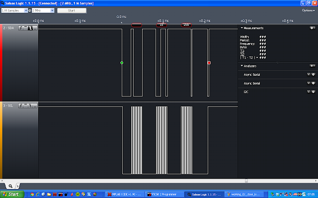
I've been using a small logic analyzer from Saleae to analyze the I2C bus. Here are a few screenshots from the transmission:
I2C transmission captured with logic analyzer from Saleae.

I2C transmission in close up, to show message translation.
I need to return the logic analyzer this week, so I need to replace it with something else. I'm thinking about testing out the logic analyzer in the PicKit2.

Wednesday, October 2, 2013

PIC12F1822 UART loop test

A good way to start playing with the UART interface of a microcontroller is to do a loop test. You simply receive a character and send it right back. The PICKIT2 has a built in UART tool which is perfect for experimentation, since you can program the device and test the UART without disconnecting the PICKIT2.

I've set the baud rate to 31500 symbols/s, since this is the MIDI standard.

UART loop test using the PICKIT2 UART tool.


Loop test source code

1:  //Uart RX/TX loop test using PIC12F1822  
2:  #include <xc.h>  
3:    
4:  //Configuration bits  
5:  #pragma config WDTE=OFF, PWRTE = OFF, MCLRE=OFF, BOREN=OFF, FCMEN=OFF, CLKOUTEN = OFF, IESO=OFF, FOSC=INTOSC, CPD=OFF, LVP = ON, BORV = 0  
6:    
7:  void main()  
8:  {  
9:    //Set all I/O's to digital  
10:    ANSELA = 0x00;  
11:    
12:    //0 Internal oscillator, 3 <fosc> on, 6-4 4MHz  
13:    OSCCON = 0b01101000;  
14:    
15:    //Interrupt controller  
16:    //6 Peripheral interrupt enabled  
17:    //7 Global interrupt enabled  
18:    INTCON = 0b11000000;  
19:    
20:    //TRISA  
21:    //RA1 set as input, all other IO's set as output  
22:    TRISA = 0b0000010;  
23:    
24:    //Free running bad rate timer is 7  
25:    SPBRGH = 0x00;  
26:    SPBRGL = 0x07;  
27:    
28:    //TXSTA: TRANSMIT STATUS AND CONTROL REGISTER  
29:    //8-bit transmission, transmit enable, asynchronous mode, high baud rate selected  
30:    //Baud rate is FOSC/[16 (n+1)] = 4MHz/(16 (7+1)) = 31250, approx 31500 symbols/sec  
31:    TXSTA = 0b10100110;  
32:    
33:    //RECEIVE STATUS AND CONTROL REGISTER  
34:    //Serial port enabled, continuous receive enabled  
35:    RCSTA = 0b10010000;  
36:    
37:    //PERIPHERAL INTERRUPT ENABLE REGISTER  
38:    //USART Receive interrupt enabled  
39:    PIE1 = 0b00100000;  
40:    
41:    //Loop forever  
42:    while (1)  
43:    {  
44:    }  
45:    
46:  }  
47:    
48:  //Interrupt service routine  
49:    
50:  interrupt void isr(void)  
51:  {  
52:    
53:    //If receive interrupt is triggered, transmit received symbol  
54:    if (RCIF)  
55:    {  
56:      TXREG = RCREG;  
57:    }  
58:    
59:    return;  
60:  }  

Sunday, September 29, 2013

Midi to control voltage converter

I've started working on this little circuit which will allow me to use a MIDI keyboard as control voltage for my VCO. Since MIDI is a serial protocol, I will need a microcontroller to interpret these signals. I will also need a DAC to get my control voltages. The DAC needs to be of the higher bit-type, since the VCO will need careful tuning to sound nice. I didn't find any simple microcontroller with more than 5 bits DAC, which is all little small. I did however find a nice cheap combo. A 12-bit I2C controlled DAC, MCP4725, and a 8 pin microcontroller with built in support for both UART and I2C, PIC12F1822. The DAC needs a voltage reference as both reference and supply, ZRC400F01 seems to work. All components are on the cheap and costs me less than 3€ for the lot. DAC and reference are small, surface mount components, so they are trickier to prototype with.
Midi 2 VCO converter, first steps. 

DAC

The DAC part can be seen to the right in the schematic. I've tested it out using an Aardvark I2C host adapter I borrowed from work, and it seems to work fine. When I choose the voltage reference, I thought that the 4.096V reference would fit well with a 12 bit DAC (0.001V/bit), but the DAC isn't perfectly rail to rail, so I effectively get a 0-4V DAC. I might just upgrade this with a 5V reference instead. Ideally it would be better with a higher voltage DAC since I intend to build a 1 octave/V VCO, and 0-4 V only gives me 3 octaves (4 if I upgrade to 5 V).

Microcontroller

Microcontroller  is seen to the left in the schematic. The symbol for the PIC doesn't have the correct pin descriptions, but is generally the same as the one I use, regarding supply, IO's and programming pins. I made a hello world program that blinks an LED using interrupts. This may seems simple, but it gives me a starting point where I know that IO's, clocks and interrupts are working. 
Next thing will be getting some UART communication working, and connecting it to the I2C bus.
Some Hello World!-action. Microcontroller to the right, DAC and reference to the left.

Microcontroller source code

1:  //Hello world with LED connected to RA0 on a PIC12F1822  
2:    
3:  #include <xc.h>  
4:    
5:  //Configuration bits  
6:  #pragma config WDTE=OFF, PWRTE = OFF, MCLRE=OFF, BOREN=OFF, FCMEN=OFF, CLKOUTEN = OFF, IESO=OFF, FOSC=INTOSC, CPD=OFF, LVP = ON, BORV = 0  
7:    
8:    
9:  void main()  
10:  {  
11:    //0 Internal oscillator, 3 <fosc> on, 6-4 31kHz  
12:    OSCCON = 0b00000000;  
13:    
14:    //Interrupt controller  
15:    //5 Timer0 overflow interrupt enabled  
16:    //7 Global interrupt enabled  
17:    INTCON = 0b10100000;  
18:    
19:    //Timer0  
20:    TMR0 = 0x00;  
21:    
22:    //Option Register  
23:    //2-0 Prescaler 1:4  
24:    //3 prescaler assigned to Timer0  
25:    //4 timer edge, high to low  
26:    OPTION_REG = 0b11010001;  
27:    
28:    //TRISA  
29:    //All A I/O's are set as outputs  
30:    TRISA = 0b0000000;  
31:    
32:    //PORTA  
33:    //RA0 is set  
34:    PORTA = 0b00000001;  
35:    
36:    //Loop forever, interrupts when Timer0 overflows  
37:    while(1)  
38:    {  
39:    }  
40:    
41:  }  
42:    
43:  //Interrupt routine  
44:  interrupt void isr (void)  
45:  {  
46:    //Ghost register of PORTA  
47:    int GPORTA;  
48:    
49:    //Read latch A into ghost register  
50:    GPORTA = LATA;  
51:    //Toggle bit 0  
52:    GPORTA = GPORTA^(1<<0);  
53:    //Write back into port register  
54:    PORTA = GPORTA;  
55:    
56:    //Clear interrupt flag  
57:    TMR0IF = 0;  
58:      
59:    return;  
60:  }  
61:    

Saturday, September 14, 2013

White Noise Generator + updated keyboard and mixer

Keyboard and mixer

I updated the keyboard by buffering the output with an emitter follower op amp. First I used a rail to rail op amp from microchip: MCP6271. I did forget that it had a maximum power spec of 6V, and I fed it 9V, so it started smoking after a while. It did work for quite a some time though... I replaced it with a ua741, but needed to fed that one with +-9V, to get a low enough output voltage. I really need to stock up on op amps...
 The mixer was updated with some 1% resistors for the inverter. I should probably use 1% resistors for the unity gain input and feedback resistor, to get a gain closer to 1 for that input. I also AC-coupled the other input, since DC-coupled signals puts the synthesiser out of tune.
Updated mixer schematic


White Noise Generator

I also built a simple white noise generator. It works by putting a NPN transistors base-emitter junction in reverse bias and overcoming the breakdown voltage of about 6V. By doing this, the junction will create white noise. Since the junction will conduct at first, and when it conducts the emitter voltage will drop, causing the transistor to stop conducting, which builds up the voltage above breakdown again, and so on. This happens really fast and thus noise is produced. The noise is very low voltage. I couldn't pick up the unamplyfied noise with my scope, and amplifying it with a 10000 gain opamp amplifier barely made it visible above the noise floor of the scope. So I used two opamps and amplified to the whole swing af the opamps.
 The noise can now be mixed  with the VCO control voltage, but it really creates a very broken and harsh sound. So it's probably better to mix it with the VCO output. I'll try that next time. I should probably also build another mixer, so that I can mix a wave with the control voltage, and the noise with VCO output, now I need to choose...
 On the next mixer I will get an op amp that can be turned off, so that I can use a gate signal from the keyboard to turn it on when playing a tune. As it is now, a high amplitude AC-coupled signal can have levels high enough to stimulate a VCO tune, which cause background noise when not pressing any buttons.
White Noise Generator schematic

White Noise Generator and mixer sharing the same quadruple op amp.


Monday, September 9, 2013

Summing amplifier mixer

I made a simple mixer for the synthesiser . It's a summing amplifier with two inputs, of which one is AC-coupled with a 47uF cap, so that the created high pass filter will still pass 0.1Hz signals through. My first idea was that this could be used to add some signal on top of the voltage passed on to the VCO, to create some pitch vibrato. This idea worked, but still failed, since the synthesiser gets totally out of tune when doing this. The problem is that what I thought of as unity gain from the summing amplifier, isn't really unity gain, since I'm using 5% resistors. The small change in gain can throw of the tuning, there is as little as 200mV difference between two semitones.
 Also, the simple keyboard uses a wild variety of potentiometers, who's resistance will be a part of the feedback network of the summing amplifiers. Thus the keyboards output needs buffering. I'll get back on the topic as soon as I'm done doing that.

Summing amplifier mixer, schematic

Summing amplifier mixer, actual board

Thursday, September 5, 2013

Simple VCO keyboard

To be able to play a bit on the synthesiser, I made a simple keyboard out of some old scrap I had in the junk bin. The construction is very simple: a potentiometer as voltage divider between rail and ground and a push button between output and wiper. Each button is tuned with the potentiometer and output is connected to the VCO. I made a full octave, starting with C, which gives 12 buttons and 12 potentiometers. Its was a bit boring to assemble, but works great.
VCO keyboard

Sunday, September 1, 2013

Unstable opamps, VCO and low pass filter

As I mentioned earlier there was some oscillation problems with the VCO sawtooth output. The problem was easily solved by biasing the opamp high. This makes the opamp faster and gives it a higher phase margin, thus making it more stable when driving capacitive loads. Since this solved the problem, I removed the opamp buffer from the output. The low pass filter had the same kind of issue, and it was solved in the same way.
 The filter also suffered from some clipping, which I solved by replacing R1 with a potentiometer and trying out the best value, which was 3.45k\(\Omega\). When P1 was set to the lowest resistance, there where some oscillations in the output. This was solved by putting 1k\(\Omega\) in series with each potentiometer terminal. I'll see if I can get my function generator to sweep out a bode plot of the filter, to see some details on it's characteristics.
Updated active filter schematics

 To get some higher tones out of the VCO, replaced C1 with a smaller capacitor. I needed a few tries to find a good match. A small capacitor gave a higher frequency, but the wave forms got scewed, probably due to unmatched resistors in the input stage. A smaller capacitor also raised the lower end frequency too high. This shows that I probably need to find a better VCO design, to get a higher bandwidth.

Thursday, August 29, 2013

Low pass filter and VCO update

VCO update

I added an LED to indicate the oscillation frequency of the VCO.  I also found an old power amplifier in the electronics junk room in the basement. From that I harvested a whole bunch of RCA jacks and a couple of very nice potentiometers. The jacks will be great for connecting modules, since RCA cables are shielded and easy to find/cheap. I disconnected the voltage source for the VCO, so now you have a choice of connecting either the voltage divider or another external voltage source to control the VCO.

I also discovered that when connecting the triangle wave output to a speaker (+ amplifier) i got some high frequency oscillations superimposed upon the triangle wave. I think these oscillations arise due to driving a capacitive load which is in the cabling or perhaps a DC-block capacitor in the amplifier. I'm going to deal with this later, but the TLC721 is a programmable opamp and is currently programmed as low biased. This is the slowest and most energy effective mode with a phase margin of 34°. The high bias mode has a phase margin of 47°, which might make the difference in this case. A first I thought that the output needed to be buffered, so I added an emitter follower opamp. This removed the oscillations from the original output opamp, but transferred the problem to the buffer output instead.

Superimposed oscillations on sawtooth wave. Upper waveform is from stage connected to amplifier. Lower waveform is from stage before output buffer.

Active Low Pass Filter

From The Art of Electronics, I took the simplest active filter circuit i could find. It's a two pole low pass Butterworth filter, which consists of two identical capacitors and two identical resistors, making up the filter, one opamp and two resistors for gain control.
Having two identical resistors that make up the filter gives a problem when making a variable filter, since you will need a double gang potentiometer. Lucky enough I found a couple of those in the power amplifier I mentioned. I took one that goes to 50k\(\Omega\). The -3dB frequency of the filter is given by
\[f_0 = \frac{1}{2 \pi RC}\]
with the lowest frequency being 20Hz, that gives me:
\[C = \frac{1}{2\pi 50000\Omega 20\text{Hz}} = 150 \text{nF}\]
with higher cutoff frequency with lower resistance in the potentiometer.

I added RCA jacks and the whole thing looks like this:
Active low pass filter schematic

Active low pass filter to the right

works like expected as well...


Monday, August 19, 2013

Voltage Controlled Oscillator

I'm looking into how analogue synthesizers work and plan to build a couple of modules. The first module to build is a VCO, Voltage Controlled Oscillator. I found a simple one in The art of Electronics which i built on a copper plane, Jim Williams style.
 Schematics and images are shown below.
VCO on copper plane. A potentiometer is used as voltage source.

VCO schematic based on design from The Art of Electronics.
In The Art of Electronics, 1% resistors are used in the input stage of the first Op-Amp. I didn't have any such resistors at home, but it seems to work well with 5% resistors. Max frequency is about 50Hz, which means this design isn't very useful as instrument, but it gave me something basic to start with. Also, voltage output from sawtooth and square wave where quite different. The square wave comes from a comparator with the full supply rail as swing.
Sawtooth and square wave output from VCO.

In the junk room in my cellar, I found an old power amplifier with a lot of RCA jacks on the back, which I'll use to connect the different modules to each other. More on this topic later on.

Tuesday, August 6, 2013

Fluke 8050A Repair, Part 2

I tried out the modification suggested in the last post, but somehow I couldn't get it working. The layout of the board in the modification instruction is not the same as mine, and I guess I didn't figure out all the differences.
 Finally I ended up buying som NiCd batteries with solderlugs. I didn't buy the more expensive C-size ones, but the cheapest ones that would fit, which cost about 24€. The DMM seems to be quite good, so I figured it was worth the new batteries.
 Installing wasn't more difficult than soldering the old wires the the new batteries and now the DMM works great, both on AC and battery. The new batteries are specified to almost the double amount of charge, so I expect the DMM to be going for quite some time between charge.
Measuring voltage running on battery power

Monday, July 22, 2013

Fluke 8050A Repair, Part 1

We scrapped an old Fluke 8050A, Digital Multimeter. It's and old bench multimeter with 4.5 digits. This one has the built in rechargable battery option.


The instrument was simply dead, so I took it home to try to fix it. Accompanying the DMM was an excellent manual, with schematics and service instructions.
 Taking a look at the motherboard showed some blackness around a LM317 linear regulator, so I took that out and measured the resistance at the mounting wholes of the regulator, to see if anything had shorted out. Resistance was as expected. I replaced the regulator with one I found in my junk pile. No difference. The regulator got really hot. 
Replaced regulator is the TO package located just below transformer.

I measured some test voltage points that where described in the manual, and they all showed a somewhat lower voltage than expected. So the problem is probably with the power delivery.
 I looked around the net and found some tips about modifying the 8050A so that it works without batteries. Hm, hadn't thought about it not working without it's batteries. Of course, Ni Cd batteries from the late 70's, early 80's, won't work properly today. Because of this, I had already taken the batteries out, thinking that it would work without them, as many modern pieces of equipment does.
 To test if this was the problem i connected an external 4.8V power supply to the battery terminals, to emulate a working battery. Voila! The display lights up, but is missing some segments.
 The segments are fixed by removing the LCD display and cleaning the contact surfaces. Here's the result:
Fluke 8050A, with emulated battery, measuring the resistance of a resistor.
So the question is now, do I replace the old batteries? Four new Ni Cd C batteries cost about 40€, which  I should think is very close to the value of a working instrument... It would be nice to have the old instrument in original condition though. Modifying the DMM to work without batteries is pretty easy and is described here. I will have to think about what to do, and will return in part two to tell what I ended up doing.

Saturday, July 20, 2013

Finally, a proper workbench

i finally got a proper workbench installed at home! This is really good for me, since I usually only have an hour or so on my projects, after my kids are put to bed. Before I had all my equipment in a cupboard. So to start working, I needed to set everything up on the kitchen table. When I'd finished working, everything needed to be put back. So, not a lot of time for working...
 Now I've got a workbench where I can leave projects lying and work on them for five minutes, if that's what I have.


The metal detector is yet to be finished, I'll do that soon. Right now, as can be seen in the picture, I'm trying to fix a broken Fluke 8050A, which I salvaged from work. That will be in my next post.

Tuesday, February 5, 2013

Metal detector part 3, Darlington emitter follower

One thing I suddenly realized when trying to figure out what frequencies we have in the oscillator nodes, the probes will affect the circuit. The Tektronix probe has 10M\(\Omega\) and 10pF. Our nodes have about 2 pF and between 20k and 1.5\(\Omega\), so they will change the effective values. What we need is the Darlington emitter follower, which will introduce about the same impedance and capacitance as the probe, but with the difference that the follower will always be a part of the circuit.
The circuit now looks like this:


 The output from Q4's emitter is seen here:


The two outputs show the mixed down frequencies when the local oscillator is tuned to its two extremes.
The lowest frequency is about 13kHz, which is probably a bit high. But let's wait until we can listen to the signal until we fine tune it some more.
The next step will be to define a push/pull amplifier for the loudspeaker. By the way, a loudspeaker might draw a bit to much power, so I'll see if I can use a summer from a PC motherboard instead. I'll need to measure its impedance first, to make the calculations for the amplifier.

Saturday, January 26, 2013

Metal detector part 2, the LM386

OK, I made some mistakes in the last post, so let's take a step back and revisit parts of it.
 Last time I wrote that we wanted a low impedance in the connection between the two oscillators. I also calculated the impedance in that node at 20Hz, since that's the mixed frequency we will listen to when we look for treasure.
 Wrong! The frequency we are mixing is around 400kHz, the lower frequency comes in the next node. So we need to make new impedance calculations to match the pull up/pull down network.
 But there is more. I did try to connect the two oscillators with large capacitors, but suddenly the two oscillators where oscillating together. What's happened? I'm not completely sure about the mechanism, but having a small impedance at the emitter will load the emitter significantly, compared to the 22k\(\Omega\) resistor.  Loading the emitter in the oscillator is bad, since it would remove the small charge injection into the oscillation tank. We need the opposite, just like the original EDN article, which uses 1.2pF capacitors. I found a couple of 2.2pF capacitors, which will do. This gives us
\[|Z|   = \frac{1}{2 \pi 400\text{kHz} 2.2\text{pF}} = 181\text{k}\Omega\]. Pull up/pull down resistors with a parallel resistance of 1.8M\(\Omega\) should suffice.
 Now comes the next problem. The audio amplifier we are building needs to have a high impedance input, but BJT's are usually hard to design as high very high impedance emitter followers. I asked an experienced colleague about the problem and he suggested that I look in the data sheet of the audio amplifier that EDN use, to see if it shows how the transistors in the IC connected. Great idea!
 Look at the data sheet page two. At the inputs (pin 2 and 3) you can see cascaded transistors. Connecting transistors this way is called a Darlington connection and it gives a very high input impedance, (\(h_{fe1}\cdot h_{fe2}\cdot R_e\)), and a very high gain. This is what we will try out as the first part of our audio amplifier. But now that we are at it, we might as well see if we can understand the rest of the LM386.
 The Darlington inputs are connected to a differential amplifier, the two mirrored npn's below the input stage. It amplifies the difference between the two inputs. The diff amplifiers output goes to a push-pull amplifier. This one has a transistor connected to ground (straight below the two diodes), that compensates for temperature induce gain change in the the rest of the amplifier. The lower amplifier stage has a Sziklai connected stage instead of a single transistor. It basically has the same function as the Darlington connection, it gives a higher input impedance and higher gain. If you want to know more about these circuits, I highly recommend reading chapter two of Horowitz & Hill(1989).
 By the way, does anyone know what the circle with the arrow, at the top of the diagram, means? My guess would be some kind of diode. In Horowitz & Hill(1989), page 93, there is a resistor in that position.  
This is it for now. I'll report back when I have tried the described circuit change and the Darlington emitter follower.

References
Horowitz, P., & Hill, W. (1989). The art of electronics. Cambridge university press.

Wednesday, January 16, 2013

Metal detector using Colpitt oscillators

This is a project I found through http://www.geotech1.com/. It's an old EDN article describing a very simple metal detector I thought I'd use treasure hunting with one of my daughters.

Oscillator circuits

 The basic principle is to use two oscillators. At least one of them should use an inductor as a part of the oscillator tank. The easiest design is a Colpitt's oscillator, since it only use one simple inductance together with a couple of capacitors. An LC circuit would oscillate spontaneously if it weren't for the resistance in the coil, capacitors, wires etc. To compensate for the resistance we use a transistor to give a small charge push in every oscillation. Here's an LTSpice simulation of such a circuit:

Colpitt oscillator

The output of the oscillator is taken from the emitter, and if you look at the simulated currents in the transistor, you will see some strange oscillations. These come from the base going above the collector for a short period of time. They will probably not be present in the real circuit due to internal resistance in the various elements of the circuit (this will of course be checked in reality..)

The oscillator frequencies depends on the inductance of the coil. By winding a big air coil, the frequency of the oscillator will change when the surrounding permeability changes according to this formula:
\[L = \mu k\]
where L is inductance, \(\mu\) is permeability and k is a constant depending on the physical shape of the coil.

Frequency mixing

Frequency is typically around 400kHz, so we need to convert it down to audio levels if we want to use a loudspeaker as indicator. This is done using a local oscillator with a fixed frequency. The two oscillator outputs are connected via capacitors, like in the schematic below. We also need to pull the out signal somewhere, not to leave output floating. The pull up/pull down resistors are chosen to have a total resistance of 75k\(\Omega\) (you will see why when we design the audio amplifier). We can see the capacitors as output from one stage and the resistors as inputs to the next stage. One wants a low output impedance connected to a high input impedance to avoid loading the oscillator. The impedance of the capacitors are less than 7.5k\(\Omega\) according to the formula \(|Z| = \frac{1}{2 \pi f C} \approx 4000 \Omega\) at our lowest required frequency 20Hz. The capacitors and resistors make a high pass RC-filter, so we also need to check that the filter doesn't filter out sound above 20Hz. The cut-off frequency is: \(f_c = \frac{1}{2 \pi R C} \approx 1 \)Hz.
Simplified mixer circuit

 So, what will the output of this setup be? Let the capacitors be complex impedance's:
\[z_1 = \frac{-j}{2 \pi f_1 C_1}\]
\[z_2 = \frac{-j}{2 \pi f_2 C_2}\]
 The current through the resistor is the sum of the current from the capacitors.
 \[I_{C1}+I_{C2}=I_R\]
The voltage drop over R is
\[V_{out} = R \cdot I_R = R (I_{C1}+I_{C2})\]
The current from the capacitors will be:
\[I_{C1} = \frac{V_1}{z_1} = \frac{-j\cdot V_1}{2 \pi f_1 C_1}\]
\[I_{C2} = \frac{-j\cdot V_2}{2 \pi f_2 C_2}\]
 so
\[V_{out} = R \left (\frac{-j\cdot V_1}{2 \pi f_1 C_1}+\frac{-j\cdot V_2}{2 \pi f_2 C_2}\right)\]
Since we are dealing with real voltages, the output voltage will be
 \[|V_{out}| = R \left (\frac{\sin(2 \pi f_1 t)}{2 \pi f_1 C_1}+\frac{\sin (2 \pi f_2 t)}{2 \pi f_2 C_2}\right )\]
When adding two sine waves, we can use this identity:
\[\sin(\alpha)+\sin(\beta) = 2 \sin\left (\frac{\alpha + \beta}{2}\right ) \cos\left (\frac{\alpha - \beta}{2}\right )\]
 Without actually calculating the amplitude of the resulting wave ( which we are less interested in) we can see that the resulting wave will have both the added and the subtracted  frequencies of the two original waves. It will look for example like this,
20 beats per second from a 400.00kHz and a 400.02KHz sine wave.
 By using a local oscillator with a frequency very close to the variable oscillator, we can generate a frequency component in the audible range that is proportional to the permeability close to the search coil.
 The first step is to build the oscillators  and trim them so they are close enough to each other. The second step will be building an audio amplifier to amplify the mixed signal. In the EDN article, they use a dedicated audio amplifier chip. I will build the amplifier from transistors, since that is one of the purposes of this project, to learn about transistor (BJT) electronics.


Sunday, January 13, 2013

Boost regulator efficiency meter

This is a project I've been working on from time to time for a while now, but now it's time to wrap it up and document it.  The whole thing started with me building a couple of boost regulators for charging the cell phone (inspired by Minty Boost). I used one regulator from LT and one from TI, and I wanted to compare their energy efficiency.
Boost regulator from LT (LT1302)
Boost regulator from TI (LM2700MT-ADJ)
 To do this one needs to measure power on both sides of the regulator and present the fraction of the output to the input. This was done using a PIC 16F690, which has plenty of IO's and a 10 bit ADC with several channels. Measurements can be done using four ADC channels and the result can be presented using LED's on the rest of the IO's.
Voltage measurements where done by connecting the 3 volt regulator side directly to an ADC channel. Since the PIC is thought to be running from 4.5V battery power, this will be the absolute upper limit of what the ADC can measure. The output of the regulator is 5V, so that voltage was connected to the ADC through a voltage divider.
 Current is measured by measuring the voltage drop over a milliohm resistor in series with the load. We don't want the resistor to load the circuit to much, but a small resistor mean a small voltage drop, so we will use an operational amplifier as a differential amplifier to amplify the drop before it is measured with the ADC.
 I generally try to use scrapped or salvaged parts and I had two milliohm resistors lying around at work, one 0.1 Ohms and one 0.02 Ohms, so I used those together with a couple of rail-to-rail op-amps (Microchips
MCP6271) that I bought. I started out experimenting with some old LM741's, but they needed a few volts both over and above their maximum output, which did not fit well with my ambition to power the circuit with three batteries.
Lab setup. 
Finished board. 
 The gain of the differential amplifier was chosen so that a current of 2A would give an output signal of around 4 volts. The schematic of the circuit can be found here. The PCB was made using double sided toner transfer, which didn't work all that good. Also, I mixed up the power terminals of the op-amps (fixed in the schematic above), so there were quite a few straps made.
 The PIC source code can be found here. The code does the job as long as one is only interested in comparing regulators. The code is only calibrated against one ADC channel at a time and test measurements showed an efficiency of under 50% for both of the regulators, which seems a bit low. It would probably be better to use two known power inputs and calibrate efficiency against those.
 Calibration was done using a known current source. By knowing the current ,\(I_{in}\), and reading the ADC binary output \(I_{bin}\), we can get the conversion factor (k) if we have the linear relationship \(I_{in}=k \cdot I_{bin}\). By making a few measurements of this kind we can use the very smart website http://www.wolframalpha.com/ to get a linear fit with the measured data. Here's one of the calculations (actually for a voltage input, but the principle is exactly the same) using the command: linear fit {{1023,5.44},{511,2.7},{255,1.33},{127, 0.65}}. In the end, what we will calculate in matter of ADC outputs is \(E=(k_{out-I} \cdot I_{out-bin} \cdot k_{out-V} \cdot V_{out-bin})/(k_{in-I} \cdot I_{out-bin} \cdot k_{in-V} \cdot  V_{out-bin)}\), and hopefully we can group all k's into a nice, single, integer (0.6 in our case, not so nice...). The observant reader will notice that there is also an offset term missing in \(I_{in}\), which is actually there in the Wolfram Alpha output. I haven't looked into this yet, but for now I will ignore this since I actually don't a whole lot of accuracy and the offset is pretty small. A complete error analysis of the measurement system would be interesting but time consuming, maybe I'll come back to that on a rainy day. (By the way, I used MathJax to display mathematical equations...)
 Sample rate of the ADC's are adjusted to what looks stable on the output LED's, which is quite a lot slower than what could be achieved. An algorithm for more samples than LED updates would probably be good. Let's see the present code as work in progress, shall we?
 This is a topic that can be explored deeply, both the measurements aspect and the regulator aspect. Right now, however, I'm eager to get my hands on a couple of other projects, so the efficiency meter will be put on the shelf for a while. I'm sure I'll come back to it in the future though...