I have now managed to configure the PIC to send a message over the I2C bus. It was a bit tricky, but now everything seem to work. Here's the source:
1:  //Uart RX/TX loop test and I2C transmission test using PIC12F1822
2:  #include <xc.h>
3:  //Configuration bits
4:  #pragma config WDTE=OFF, PWRTE = OFF, MCLRE=OFF, BOREN=OFF, FCMEN=OFF, CLKOUTEN = OFF, IESO=OFF, FOSC=INTOSC, CPD=OFF, LVP = ON, BORV = 0
5:  //This symbol is needed so that __delay_ms() gives a correct delay time
6:  #define _XTAL_FREQ 4000000
7:  int transmitCycle; //Counter for I2C transmission cycle steps, which are carried out in the interrupt service routine
8:  void main()
9:  {
10:    int transmitCycle = 1;
11:    int GPORTA; //Port A ghost variable
12:    PORTA = 0x01; //Set RA0 to light LED
13:    //I2C baud rate generator set to Fclock = Fosc/(4(SSP1ADD+1)) = 4MHz/(4(2+1))=333kHz
14:    SSP1ADD = 0b00000010;
15:    //SSP1STAT SSP1 STATUS REGISTER
16:    //SSP1STAT = 0b0000 0000; //default
17:    //SSP1CON1 SSP1 CONTROL REGISTER 1
18:    //I2C Master mode
19:    //Serial port pins SDA and SCL enabled
20:    SSP1CON1 = 0b00101000;
21:    //SSP1CON2 SSP1 CONTROL REGISTER 2
22:    //SSP1CON2 = 0b00000000; //default
23:    //SSP1CON3 SSP1 CONTROL REGISTER 3
24:    //SSP1CON3 = 0b00000000; //default
25:    //Set all I/O's to digital
26:    ANSELA = 0x00;
27:    //ALTERNATE PIN FUNCTION CONTROL REGISTER
28:    //Set UART RX/TX to pins RA5/RA4
29:    APFCON = 0b10000100;
30:    //0 Internal oscillator, 3 <fosc> on, 6-4 4MHz
31:    OSCCON = 0b01101000;
32:    //Interrupt controller
33:    //6 Peripheral interrupt enabled
34:    //7 Global interrupt enabled
35:    INTCON = 0b11000000;
36:    //TRISA
37:    //RA1,2,5 set as input, all other IO's set as output
38:    TRISA = 0b00100110;
39:    //Free running bad rate timer is 7
40:    SPBRGH = 0x00;
41:    SPBRGL = 0x07;
42:    //TXSTA: TRANSMIT STATUS AND CONTROL REGISTER
43:    //8-bit transmission, transmit enable, asynchronous mode, high baud rate selected
44:    //Baud rate is FOSC/[16 (n+1)] = 4MHz/(16 (7+1)) = 31250, approx 31500 symbols/sec
45:    TXSTA = 0b10100110;
46:    //RECEIVE STATUS AND CONTROL REGISTER
47:    //Serial port enabled, continuous receive enabled
48:    RCSTA = 0b10010000;
49:    //PERIPHERAL INTERRUPT ENABLE REGISTER
50:    //USART Receive interrupt enabled
51:    //Synchronous Serial Port (MSSP) Interrupt Enable
52:    PIE1 = 0b00101000;
53:    //Delay 5 seconds before I2C transmission
54:    __delay_ms(5000);
55:    SEN = 1;
56:    //Loop forever
57:    while (1)
58:    {
59:      //Small routine for blinking RA0 every five seconds
60:      //I2C transmission carried out when LED goes off the first time after power on
61:      //Blinking continues after I2C transmission, as and indication that controller is running
62:      //Read latch A into ghost register
63:      GPORTA = LATA;
64:      //Toggle bit 0
65:      GPORTA = GPORTA^(1 << 0);
66:      //Write back into port register
67:      PORTA = GPORTA;
68:      //Delay five seconds
69:      __delay_ms(5000);
70:    }
71:  }
72:  //Interrupt service routine
73:  interrupt void isr(void)
74:  {
75:    extern int transmitCycle;
76:    //I2C transmission concists of several interrupt events, variable transmitCycle is used to step through these events
77:    //The first interrupt comes with the start condition, SEN, is set.
78:    if (SSP1IF)
79:    {
80:      //Reset SSP interrupt flag
81:      SSP1IF = 0;
82:      //Send address
83:      if (transmitCycle == 1)
84:      {
85:        SSP1BUF = 0xC0;
86:      }
87:      //Send first data byte
88:      if (transmitCycle == 2)
89:      {
90:        SSP1BUF = 0x0F;
91:      }
92:      //Send second data byte
93:      if (transmitCycle == 3)
94:      {
95:        SSP1BUF = 0xFF;
96:      }
97:      //Send stop condition
98:      if (transmitCycle == 4)
99:      {
100:        PEN = 1;
101:      }
102:      //Stop is complete, ready to transmit again
103:      if (transmitCycle == 5)
104:      {
105:        transmitCycle = 0;
106:      }
107:      transmitCycle += 1;
108:    }
109:    //If USART receive interrupt is triggered, transmit received symbol
110:    if (RCIF)
111:    {
112:      TXREG = RCREG;
113:    }
114:    return;
115:  }
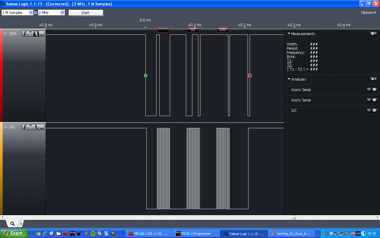 |
| I2C transmission captured with logic analyzer from Saleae. |
 |
| I2C transmission in close up, to show message translation. |
I need to return the logic analyzer this week, so I need to replace it with something else. I'm thinking about testing out the logic analyzer in the PicKit2.
No comments:
Post a Comment